Toyota Tundra (2015 year). Manual - part 2936


  Index      Toyota     Toyota Tundra (2015 year) - Service and Repair Manual


Search            copyright infringement  


Content   ..  2934  2935  2936  2937   ..


Toyota Tundra (2015 year). Manual - part 2936


Last Modified: 9-16-2014

6.6 R

Doc ID: RM000002W3C01FX

Model Year: 2015

Model: Tundra

Prod Date Range: [08/2014 -           ]

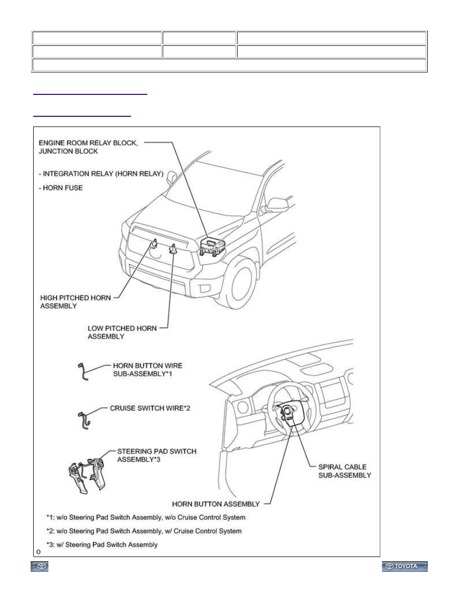
Title: HORN: HORN SYSTEM: PARTS LOCATION; 2015 MY Tundra [08/2014 -        ]

PARTS LOCATION

ILLUSTRATION

HORN: HORN SYSTEM: PARTS LOCATION; 2015 MY Tundra [08/2...

Last Modified: 9-16-2014

6.6 U

Doc ID: RM000002W3F01JX

Model Year: 2015

Model: Tundra

Prod Date Range: [08/2014 -           ]

Title: HORN: HORN SYSTEM: SYSTEM DIAGRAM; 2015 MY Tundra [08/2014 -        ]

SYSTEM DIAGRAM

HORN: HORN SYSTEM: SYSTEM DIAGRAM; 2015 MY Tundra [08...

Last Modified: 9-16-2014

6.6 T

Doc ID: RM000002W3D01IX

Model Year: 2015

Model: Tundra

Prod Date Range: [08/2014 -           ]

Title: HORN: HORN SYSTEM: PROBLEM SYMPTOMS TABLE; 2015 MY Tundra [08/2014 -        ]

PROBLEM SYMPTOMS TABLE

HINT:

Horn system

SYMPTOM

SUSPECTED AREA

SEE PAGE

Horn does not sound

HORN fuse

-

Low pitched horn assembly

High pitched horn assembly

Integration relay (HORN relay)

Spiral cable sub-assembly

Horn button wire sub-assembly*1

-

Cruise switch wire*2

-

Steering pad switch assembly*3

Horn button assembly

Harness or connector

-

*1: w/o Steering Pad Switch Assembly, w/o Cruise Control System

*2: w/o Steering Pad Switch Assembly, w/ Cruise Control System

*3: w/ Steering Pad Switch Assembly

HORN: HORN SYSTEM: PROBLEM SYMPTOMS TABLE; 2015 MY...

Last Modified: 9-16-2014

6.6 G

Doc ID: RM0000030EL00TX

Model Year: 2015

Model: Tundra

Prod Date Range: [08/2014 -           ]

Title: HORN: INTEGRATION RELAY: ON-VEHICLE INSPECTION; 2015 MY Tundra [08/2014 -        ]

ON-VEHICLE INSPECTION

1. PRECAUTION

NOTICE:

After turning the ignition switch off, waiting time may be required before disconnecting the cable from the

battery terminal. Therefore, make sure to read the disconnecting the cable from the battery terminal
notice before proceeding with work 


.

2. DISCONNECT CABLE FROM NEGATIVE BATTERY TERMINAL

NOTICE:

Some systems need to be initialized after the cable is reconnected 


.

3. REMOVE INTEGRATION RELAY (UNIT E)

(a) Remove the engine room relay block cover.

(b) Using a screwdriver, detach the 2 claws and disconnect the

integration relay from the engine room relay block.

HINT:

Tape the screwdriver tip before use.

(c) Disconnect the 3 connectors.

4. INSPECT INTEGRATION RELAY (HORN RELAY)

NOTICE:


Content   ..  2934  2935  2936  2937   ..