Toyota Tundra (2015 year). Manual - part 2794


  Index      Toyota     Toyota Tundra (2015 year) - Service and Repair Manual


Search            copyright infringement  


Content   ..  2792  2793  2794  2795   ..


Toyota Tundra (2015 year). Manual - part 2794


Last Modified: 9-16-2014

6.6 A

Doc ID: RM000002ZQL01HX

Model Year: 2015

Model: Tundra

Prod Date Range: [08/2014 -           ]

Title: STEERING COLUMN: STEERING COLUMN ASSEMBLY (for Manual Tilt): INSTALLATION; 2015 MY Tundra

[08/2014 -        ]

INSTALLATION

1. INSTALL STEERING COLUMN ASSEMBLY

(a) Install the steering column with the bolt and 2 nuts.

Torque:

21 N·m {214 kgf·cm, 15ft·lbf}

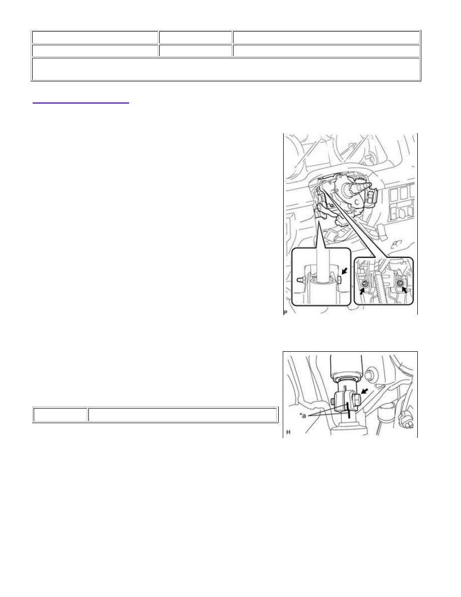
2. INSTALL NO. 2 STEERING INTERMEDIATE SHAFT SUB-ASSEMBLY

(a) Align the matchmarks on the No. 2 steering intermediate shaft

and power steering gear.

Text in Illustration

*a

Matchmark

(b) Install the bolt.

Torque:

35 N·m {357 kgf·cm, 26ft·lbf}

3. INSTALL STEERING INTERMEDIATE SHAFT ASSEMBLY

STEERING COLUMN: STEERING COLUMN ASSEMBLY (for Manu...

(a) Align the matchmarks on the steering intermediate shaft and

No. 2 steering intermediate shaft.

Text in Illustration

*a

Matchmark

(b) Install the bolt.

Torque:

35 N·m {357 kgf·cm, 26ft·lbf}

(c) Align the matchmarks on the steering column and steering

intermediate shaft.

Text in Illustration

*a

Matchmark

(d) Install the bolt.

Torque:

35 N·m {357 kgf·cm, 26ft·lbf}

(e) Install the 3 bolts and nut.

Torque:

5.0 N·m {51 kgf·cm, 44in·lbf}

4. INSTALL NO. 1 AIR DUCT SUB-ASSEMBLY

(a) Install the air duct with the bolt.

5. INSTALL LOWER NO. 1 INSTRUMENT PANEL AIRBAG ASSEMBLY 

STEERING COLUMN: STEERING COLUMN ASSEMBLY (for Manu...

6. INSTALL LOWER INSTRUMENT PANEL FINISH PANEL SUB-ASSEMBLY LH 

7. INSTALL INSTRUMENT SIDE PANEL LH 

8. INSTALL COWL SIDE TRIM BOARD LH 

9. INSTALL FRONT DOOR SCUFF PLATE LH (for Regular Cab) 

10. INSTALL FRONT DOOR SCUFF PLATE LH (for Double Cab, CrewMax) 

11. INSTALL COLUMN SHIFT SHIFT LEVER SUB-ASSEMBLY 

12. CONNECT COLUMN SHIFT TRANSMISSION CONTROL CABLE ASSEMBLY 

13. INSTALL TURN SIGNAL SWITCH ASSEMBLY WITH SPIRAL CABLE SUB-ASSEMBLY

(a) Install the turn signal switch with spiral cable to the steering

column with the clamp.

(b) Connect the 5 connectors to the turn signal switch with spiral

cable.

14. INSTALL UPPER STEERING COLUMN COVER

(a) Attach the claw to install the upper steering column cover.

(b) Attach the 4 clips.

STEERING COLUMN: STEERING COLUMN ASSEMBLY (for Manu...

15. INSTALL LOWER STEERING COLUMN COVER

(a) Attach the 2 claws to install the lower steering column cover.

(b) Install the 2 screws.

Torque:

2.0 N·m {20 kgf·cm, 18in·lbf}

16. ADJUST SPIRAL CABLE 

17. INSTALL STEERING WHEEL ASSEMBLY

(a) Align the matchmarks on the steering wheel and steering main

shaft.

Text in Illustration

*a

Matchmark

(b) Install the steering wheel set nut.

Torque:

50 N·m {510 kgf·cm, 37ft·lbf}

18. INSPECT STEERING WHEEL CENTER POINT

19. INSTALL STEERING PAD 

20. INSTALL LOWER NO. 3 STEERING WHEEL COVER 

21. INSTALL LOWER NO. 2 STEERING WHEEL COVER 

22. CONNECT CABLE TO NEGATIVE BATTERY TERMINAL

Torque:

5.4 N·m {55 kgf·cm, 48in·lbf}

NOTICE:

Some systems need to be initialized after the cable is reconnected 


.

23. CHECK SRS WARNING LIGHT

STEERING COLUMN: STEERING COLUMN ASSEMBLY (for Manu...


Content   ..  2792  2793  2794  2795   ..