Toyota Tundra (2015 year). Manual - part 2792


  Index      Toyota     Toyota Tundra (2015 year) - Service and Repair Manual


Search            copyright infringement  


Content   ..  2790  2791  2792  2793   ..


Toyota Tundra (2015 year). Manual - part 2792


(d) Using a screw extractor, remove the 2 tapered-head bolts, and

then remove the upper steering column with switch bracket and

the steering lock bracket from the steering column.

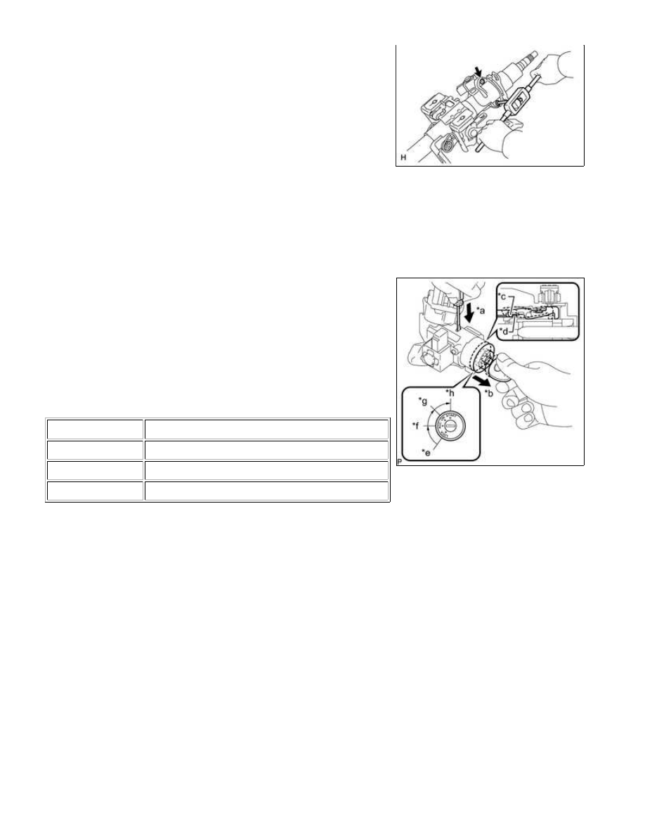
4. REMOVE IGNITION SWITCH LOCK CYLINDER ASSEMBLY

(a) Turn the ignition switch lock cylinder to the ACC position.

(b) Insert screwdriver in the steering column bracket assembly

upper as shown in the illustration. Then slide ignition switch lock

bracket assembly upper stopper.

HINT:

Make sure to pull the ignition switch lock cylinder assembly until

*a

Push

*b

Pull

*c

Claw

*c

Stopper

STEERING COLUMN: STEERING COLUMN ASSEMBLY (for Manu...

cylinder assembly.

HINT:

When the ignition lock cylinder assembly detach, a click sound is

heard.

5. REMOVE UNLOCK WARNING SWITCH ASSEMBLY

(a) Detach the 2 claws and remove the switch.

6. REMOVE KEY INTERLOCK SOLENOID

(a) Remove the 2 screws and key interlock solenoid from the

steering lock.

7. REMOVE IGNITION SWITCH ASSEMBLY

STEERING COLUMN: STEERING COLUMN ASSEMBLY (for Manu...

(a) Detach the 2 claws and remove the ignition switch from the

switch bracket.

8. REMOVE STEERING COLUMN BRACKET SPACER

(a) Using a brass bar, hammer and vise, gently strike the central

STEERING COLUMN: STEERING COLUMN ASSEMBLY (for Manu...

Last Modified: 9-16-2014

6.6 G

Doc ID: RM000002ZQM019X

Model Year: 2015

Model: Tundra

Prod Date Range: [08/2014 -           ]

Title: STEERING COLUMN: STEERING COLUMN ASSEMBLY (for Manual Tilt): INSPECTION; 2015 MY Tundra

[08/2014 -        ]

INSPECTION

1. INSPECT STEERING COLUMN ASSEMBLY

529.5 mm (1.74 ft.)

(b) Inspect the bushings.

(1) Check that the 2 bushings are securely installed to the

steering column assembly.

Text in Illustration

*1

Bushing

If the bushings are missing or damaged, replace the steering

column assembly with a new one.

(2) Check the 2 bushings for deformation and damage.

If the bushings are deformed or damaged, replace the steering column assembly with a new one.

(c) Inspect the capsules.

(1) Check that the 2 capsules are securely installed to the

steering column assembly as shown in the illustration.

Standard Dimension:

A

B

3 mm (0.118 in.)

10 mm (0.394 in.)

Text in Illustration

*1

Capsule

If the capsules are not positioned as specified, replace the

steering column assembly with a new one.

STEERING COLUMN: STEERING COLUMN ASSEMBLY (for Manu...


Content   ..  2790  2791  2792  2793   ..