Toyota Tundra (2015 year). Manual - part 2780


  Index      Toyota     Toyota Tundra (2015 year) - Service and Repair Manual


Search            copyright infringement  


Content   ..  2778  2779  2780  2781   ..


Toyota Tundra (2015 year). Manual - part 2780


INSPECTION PROCEDURE

HINT:

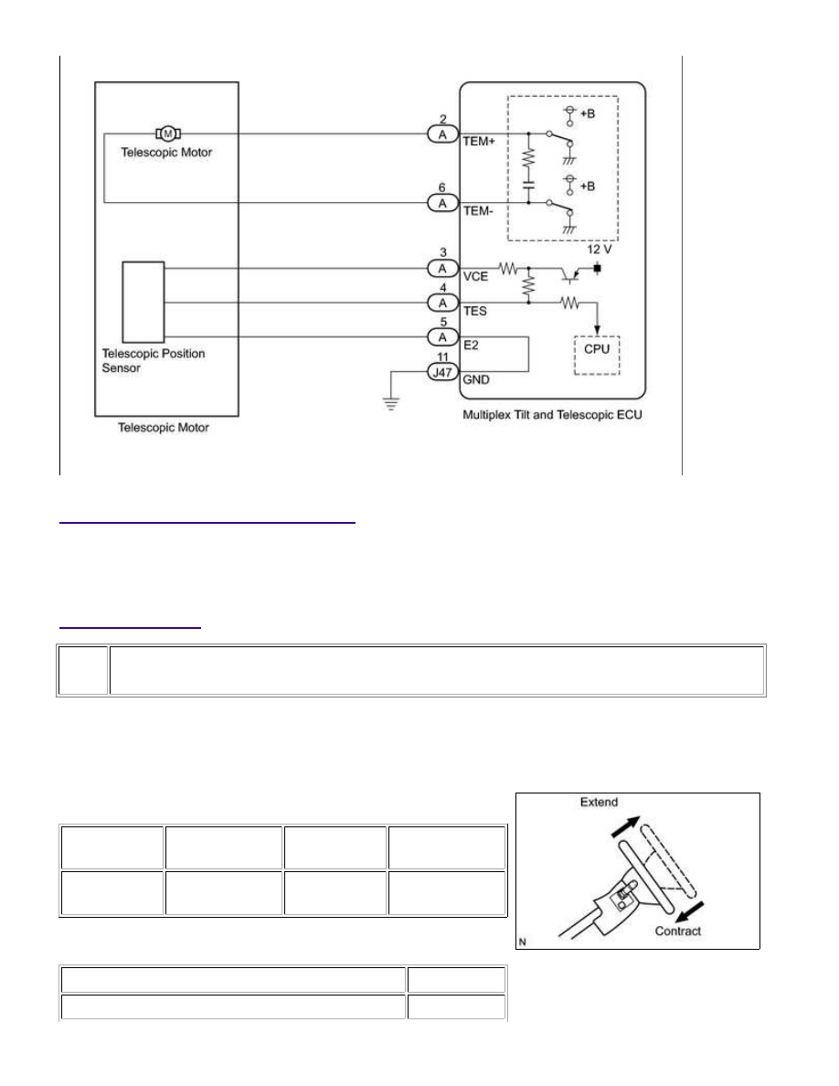
The wire harness between the multiplex tilt and telescopic ECU and telescopic motor is provided with the

steering column assembly.

PROCEDURE

1.

PERFORM ACTIVE TEST USING TECHSTREAM (TELESCO SHORT/LONG)

(a) Select the Active Test, use the Techstream to generate a

control command, and then check that the steering column
contracts and extends.

Tilt & Telescopic

TESTER

DISPLAY

TEST PART

CONTROL

RANGE

DIAGNOSTIC

NOTE

Telesco

operation

Telescopic

operation

Long / Short

-

Result

RESULT

PROCEED TO

The steering column does not contract (extend).

A

STEERING COLUMN: POWER TILT AND POWER TELESCOPIC ...

A

RESULT

PROCEED TO

The steering column contracts (extends).

B

B

GO TO STEP 3

2.

CHECK TELESCOPIC MOTOR

(a) Disconnect connector A from the multiplex tilt and telescopic

ECU.

(b) Apply 12 V battery voltage to the multiplex tilt and telescopic ECU connector. Then check the

steering wheel telescopic operation.

OK

MEASUREMENT CONDITION

SPECIFIED CONDITION

12 V battery positive (+) lead → Terminal A-2 (TEM+)
12 V battery negative (-) lead → Terminal A-6 (TEM-)

The steering column contracts.

12 V battery positive (+) lead → Terminal A-6 (TEM-)
12 V battery negative (-) lead → Terminal A-2 (TEM+)

The steering column extends

NG

REPLACE STEERING COLUMN ASSEMBLY

OK

REPLACE MULTIPLEX TILT AND TELESCOPIC ECU

3.

CHECK MULTIPLEX TILT AND TELESCOPIC ECU (VCE TERMINAL VOLTAGE)

STEERING COLUMN: POWER TILT AND POWER TELESCOPIC ...

OK

(a) Measure the voltage according to the value(s) in the table

below.

Standard Voltage:

TESTER CONNECTION SWITCH CONDITION SPECIFIED CONDITION

A-3 (VCE) - A-5 (E2)

Ignition switch ON

8 to 16 V

NG

GO TO STEP 5

4.

CHECK TELESCOPIC POSITION SENSOR

(a) Measure the voltage according to the value(s) in the table

below.

Standard Voltage:

TESTER

CONNECTION

CONDITION

SPECIFIED

CONDITION

A-4 (TES) - A-5

(E2)

Telescopic steering

contracted or extended

Pulse generation

High: 8 to 16 V

Low: Below 1 V

NG

REPLACE STEERING COLUMN ASSEMBLY

OK

REPLACE MULTIPLEX TILT AND TELESCOPIC ECU

5.

CHECK HARNESS AND CONNECTOR (MULTIPLEX TILT AND TELESCOPIC ECU -
TELESCOPIC POSITION SENSOR)

STEERING COLUMN: POWER TILT AND POWER TELESCOPIC ...

OK

(a) Disconnect connector A from the multiplex tilt and telescopic

ECU.

(b) Measure the resistance according to the value(s) in the table below.

Standard Resistance:

TESTER CONNECTION

CONDITION

SPECIFIED CONDITION

A-3 (VCE) - Body ground

Always

10 kΩ or higher

NG

REPAIR OR REPLACE HARNESS OR CONNECTOR

6.

CHECK HARNESS AND CONNECTOR (MULTIPLEX TILT AND TELESCOPIC ECU - BODY
GROUND)

(a) Disconnect the J47 multiplex tilt and telescopic ECU

connector.

(b) Measure the resistance according to the value(s) in the table below.

Standard Resistance:

STEERING COLUMN: POWER TILT AND POWER TELESCOPIC ...


Content   ..  2778  2779  2780  2781   ..