Toyota Tundra (2015 year). Manual - part 2778


  Index      Toyota     Toyota Tundra (2015 year) - Service and Repair Manual


Search            copyright infringement  


Content   ..  2776  2777  2778  2779   ..


Toyota Tundra (2015 year). Manual - part 2778


Last Modified: 9-16-2014

6.6 C

Doc ID: RM000000XZ906JX

Model Year: 2015

Model: Tundra

Prod Date Range: [08/2014 -           ]

Title: STEERING COLUMN: POWER TILT AND POWER TELESCOPIC STEERING COLUMN SYSTEM: B2610; Tilt

Position Sensor or Tilt Motor Circuit Malfunction; 2015 MY Tundra [08/2014 -        ]

DTC

B2610

Tilt Position Sensor or Tilt Motor Circuit Malfunction

DESCRIPTION

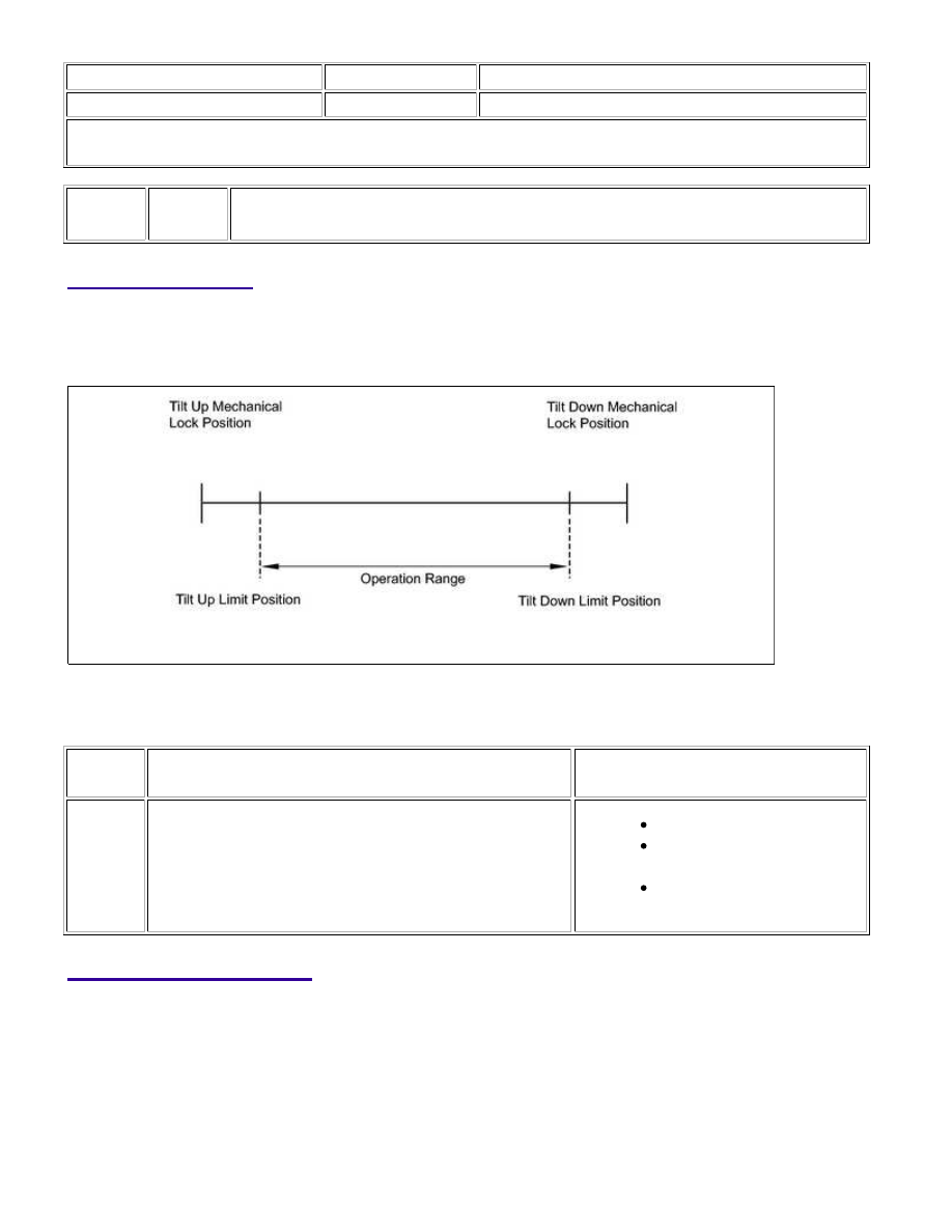
The tilt motor is operated by the power source voltage supplied from the multiplex tilt and telescopic ECU and

tilts the steering column up and down. The tilt position sensor (Hall IC) in the tilt motor detects the tilt angle of

the steering column and outputs a signal to the CPU based on that tilt.

HINT:

CODE

DETECTION CONDITION

TROUBLE AREA

B2610

Tilt operation stops within the operation range while

operating.

Harness or connector

Tilt position sensor or tilt

motor

Multiplex tilt and telescopic

ECU

WIRING DIAGRAM

STEERING COLUMN: POWER TILT AND POWER TELESCOPIC ...

INSPECTION PROCEDURE

PROCEDURE

1.

PERFORM ACTIVE TEST USING TECHSTREAM (TILT UP/DOWN)

(a) Select the Active Test, use the Techstream to generate a

control command, and then check that the steering wheel tilt
up and down.

Tilt & Telescopic

TESTER

DISPLAY

TEST PART

CONTROL

RANGE

DIAGNOSTIC

NOTE

Tilt operation

Tilt

operation

Up / Down

-

Result

RESULT

PROCEED TO

Steering wheel does not tilt up (down).

A

Steering wheel tilts up (down).

B

STEERING COLUMN: POWER TILT AND POWER TELESCOPIC ...

A

OK

B

GO TO STEP 4

2.

CHECK HARNESS AND CONNECTOR (MULTIPLEX TILT AND TELESCOPIC ECU - TILT
MOTOR)

(a) Disconnect the J47 multiplex tilt and telescopic ECU connector.

(b) Disconnect the J48 tilt motor connector.

(c) Measure the resistance according to the value(s) in the table below.

Standard Resistance:

TESTER CONNECTION

CONDITION

SPECIFIED CONDITION

J47-10 (TIM+) - J48-2 (TIM+)

Always

Below 1 Ω

J47-1 (TIM-) - J48-1 (TIM-)

Always

Below 1 Ω

J47-10 (TIM+) - Body ground

Always

10 kΩ or higher

J47-1 (TIM-) - Body ground

Always

10 kΩ or higher

NG

REPAIR OR REPLACE HARNESS OR CONNECTOR

3.

INSPECT TILT MOTOR

STEERING COLUMN: POWER TILT AND POWER TELESCOPIC ...

(a) Apply 12 V battery voltage to the tilt motor connector. Then check the steering wheel tilt operation.

OK

MEASUREMENT CONDITION

SPECIFIED CONDITION

12 V battery positive (+) lead → Terminal 2 (TIM+)
12 V battery negative (-) lead → Terminal 1 (TIM-)

The steering wheel tilts up.

12 V battery positive (+) lead → Terminal 1 (TIM-)
12 V battery negative (-) lead → Terminal 2 (TIM+)

The steering wheel tilts down.

NG

REPLACE STEERING COLUMN ASSEMBLY

OK

REPLACE MULTIPLEX TILT AND TELESCOPIC ECU

4.

CHECK HARNESS AND CONNECTOR (MULTIPLEX TILT AND TELESCOPIC ECU - TILT
POSITION SENSOR)

(a) Disconnect the J47 multiplex tilt and telescopic ECU connector.

(b) Disconnect the J48 tilt motor connector.

(c) Measure the resistance according to the value(s) in the table below.

Standard Resistance:

STEERING COLUMN: POWER TILT AND POWER TELESCOPIC ...


Content   ..  2776  2777  2778  2779   ..