Toyota Tundra (2015 year). Manual - part 2757


  Index      Toyota     Toyota Tundra (2015 year) - Service and Repair Manual


Search            copyright infringement  


Content   ..  2755  2756  2757  2758   ..


Toyota Tundra (2015 year). Manual - part 2757


in.).

(j) Recheck the total preload.

Preload (turning):

1.9 to 2.7 N*m (19.4 to 27.5 kgf*cm, 16.8 to 23.9 in.*lbf)

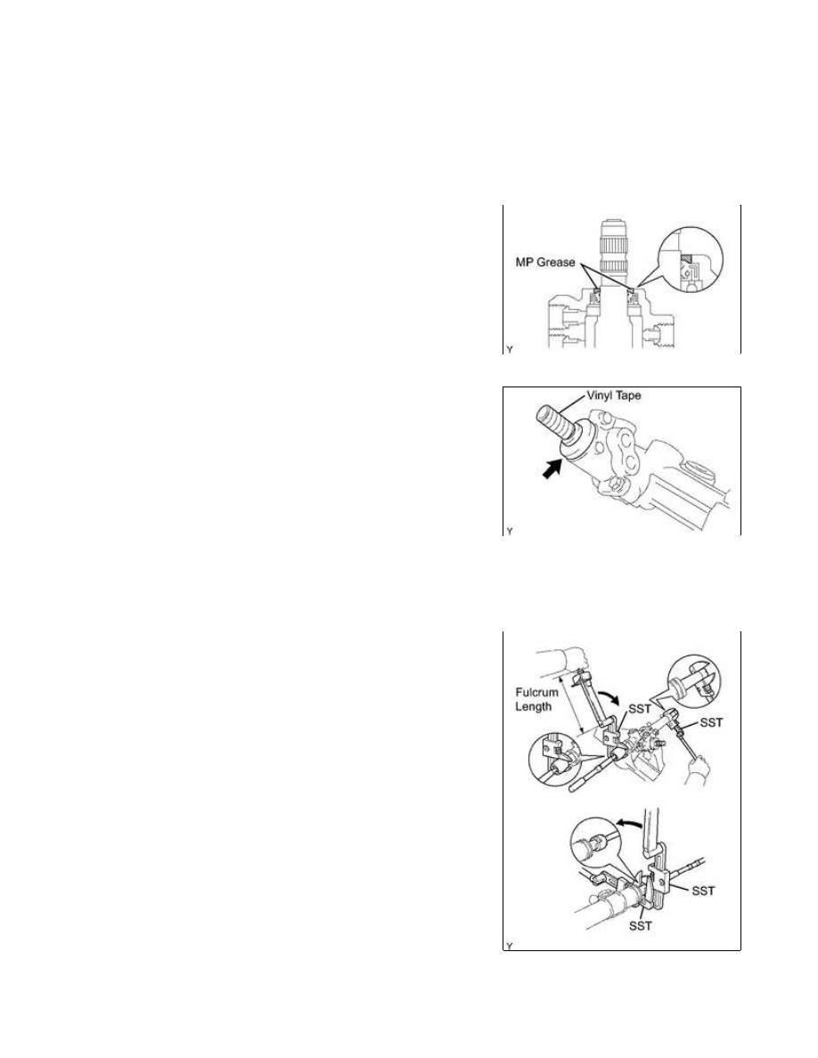
(k) Remove the RH and LH steering rack ends.

(l) Apply MP grease to the control valve as shown in the illustration.

(n) Install the dust cover onto the control valve housing.

11. INSTALL STEERING RACK END SUB-ASSEMBLY

(a) Install 2 new claw washers, and provisionally install the 2

steering rack ends.

HINT:

(b) Using 2 SST, install the 2 steering rack ends.

POWER STEERING: STEERING GEAR: REASSEMBLY; 2015 MY T...

SST: 09922-10010

Torque:

without SST -

195 N·m {1988 kgf·cm, 144ft·lbf}

with SST -

142 N·m {1448 kgf·cm, 105ft·lbf}

NOTICE:

Turn SST 09922-10010 in the direction shown in the illustration.

HINT:

NOTICE:

Avoid any impact to the power steering rack.

12. INSPECT STEERING RACK END SUB-ASSEMBLY

(a) Ensure that the steering rack end hole is not clogged with

grease.

HINT:

If the hole is clogged, the pressure inside the boot will change

after it has been assembled, when the steering wheel is turned.

13. INSTALL STEERING RACK BOOT NO. 1

14. INSTALL STEERING RACK BOOT NO. 2

15. INSTALL STEERING RACK BOOT NO. 1 CLAMP

(a) Using SST, tighten the rack boot No. 1 clamp as shown in the

illustration.

SST: 09521-24010

Clearance:

3.0 mm (0.118 in.) or less

NOTICE:

Be careful not to damage the rack boot No. 1.

16. INSTALL STEERING RACK BOOT NO. 2 CLAMP

POWER STEERING: STEERING GEAR: REASSEMBLY; 2015 MY T...

HINT:

The installation procedure for the No. 2 side is the same as that for the No. 1 side.

17. INSTALL STEERING RACK BOOT CLIP

(a) Using pliers, install the 2 rack boot clips.

NOTICE:

Make sure that each clip's claws are positioned within the area

shown in the illustration.

18. INSTALL TIE ROD END SUB-ASSEMBLY LH

Torque:

82 N·m {836 kgf·cm, 60ft·lbf}

19. INSTALL TIE ROD END SUB-ASSEMBLY RH

HINT:

The installation procedure for the RH side is the same as that for the LH side.

20. INSTALL STEERING TURN PRESSURE TUBE

(a) Coat 4 new O-rings with power steering fluid and install them onto the pressure tubes.

(b) Using union nut wrench, install the 2 pressure tubes.

Torque:

18 N·m {184 kgf·cm, 13ft·lbf}

NOTICE:

Use the formula calculate special torque values for situations for

situations where a union nut wrench is combined with a torque
wrench 


.

POWER STEERING: STEERING GEAR: REASSEMBLY; 2015 MY T...

Last Modified: 9-16-2014

6.6 A

Doc ID: RM000002H5N00MX

Model Year: 2015

Model: Tundra

Prod Date Range: [08/2014 -           ]

Title: POWER STEERING: STEERING GEAR: INSTALLATION; 2015 MY Tundra [08/2014 -        ]

INSTALLATION

1. INSTALL POWER STEERING GEAR ASSEMBLY

(a) Install the power steering gear with the 2 bolts and 2 nuts.

Torque:

120 N·m {1224 kgf·cm, 89ft·lbf}

2. INSTALL PRESSURE FEED TUBE ASSEMBLY

(a) Temporarily connect the pressure feed tube to the power

steering gear.

POWER STEERING: STEERING GEAR: INSTALLATION; 2015 MY...


Content   ..  2755  2756  2757  2758   ..