Content .. 2712 2713 2714 2715 ..
Toyota Tundra (2015 year). Manual - part 2714
OK
OK
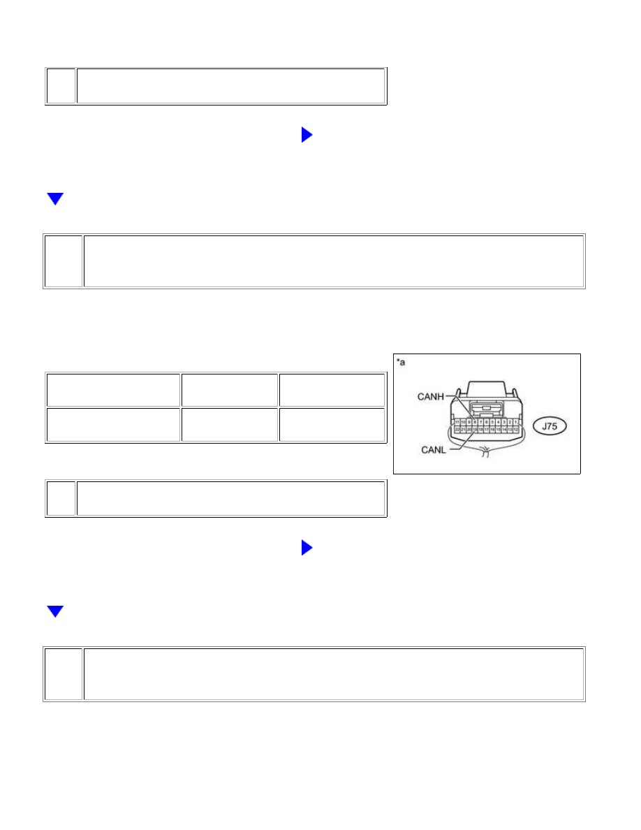
Text in Illustration
*a
NG
GO TO STEP 41
33.
CHECK FOR SHORT IN CAN BUS WIRES (NO. 1 JUNCTION CONNECTOR - SKID
CONTROL ECU)
(a) Measure the resistance according to the value(s) in the
table below.
Standard Resistance:
TESTER CONNECTION
SWITCH
CONDITION
SPECIFIED
CONDITION
J75-8 (CANH) - J75-19
(CANL)
Ignition switch off
200 Ω or higher
Text in Illustration
*a
NG
GO TO STEP 43
34.
CHECK FOR SHORT IN CAN BUS WIRES (NO. 1 JUNCTION CONNECTOR -
COMBINATION METER ASSEMBLY)
CAN COMMUNICATION: CAN COMMUNICATION SYSTEM: Short i...