Toyota Tundra (2015 year). Manual - part 2698


  Index      Toyota     Toyota Tundra (2015 year) - Service and Repair Manual


Search            copyright infringement  


Content   ..  2696  2697  2698  2699   ..


Toyota Tundra (2015 year). Manual - part 2698


OK

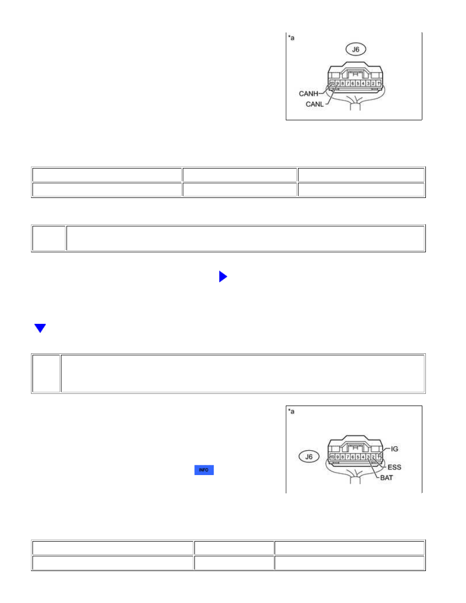
(a) Disconnect the J6 steering angle sensor connector.

(b) Measure the resistance according to the value(s) in the table below.

Standard Resistance:

TESTER CONNECTION

SWITCH CONDITION

SPECIFIED CONDITION

J6-10 (CANH) - J6-9 (CANL)

Ignition switch off

54 to 69 Ω

Text in Illustration

*a

NG

REPAIR OR REPLACE STEERING ANGLE SENSOR

CAN BRANCH WIRE OR CONNECTOR (CANH, CANL)

4.

CHECK HARNESS AND CONNECTOR (STEERING ANGLE SENSOR - BATTERY AND
BODY GROUND)

(a) Connect the cable to the negative (-) battery terminal.

NOTICE:

When disconnecting the cable, some systems need to be

initialized after the cable is reconnected 


.

(b) Measure the resistance according to the value(s) in the table below.

Standard Resistance:

TESTER CONNECTION

CONDITION

SPECIFIED CONDITION

J6-2 (ESS) - Body ground

Always

Below 1 Ω

CAN COMMUNICATION: CAN COMMUNICATION SYSTEM: Steerin...

(c) Measure the voltage according to the value(s) in the table below.

Standard Voltage:

TESTER CONNECTION

CONDITION

SPECIFIED CONDITION

J6-3 (BAT) - Body ground

Always

11 to 14 V

J6-1 (IG) - Body ground

Ignition switch ON

11 to 14 V

Text in Illustration

*a

NG

REPAIR OR REPLACE HARNESS OR CONNECTOR

OK

REPLACE STEERING ANGLE SENSOR

CAN COMMUNICATION: CAN COMMUNICATION SYSTEM: Steerin...

Last Modified: 9-16-2014

6.6 J

Doc ID: RM000004U3100BX

Model Year: 2015

Model: Tundra

Prod Date Range: [08/2014 -           ]

Title: CAN COMMUNICATION: CAN COMMUNICATION SYSTEM: Gateway ECU Communication Stop Mode; 2015

MY Tundra [08/2014 -        ]

Gateway ECU Communication Stop Mode

DESCRIPTION

DETECTION ITEM

SYMPTOM

TROUBLE AREA

Gateway ECU

Communication Stop

Mode

Either condition is met:

"CAN Gateway1" is not displayed on

the "Bus Check" screen.

"Gateway ECU Communication Stop

Mode" in "DTC Communication Table"

applies.

Power source or inside of

network gateway ECU

Network gateway ECU

CAN branch wire or

connector

Network gateway ECU

For vehicles with a blind spot monitor system.

WIRING DIAGRAM

CAN COMMUNICATION: CAN COMMUNICATION SYSTEM: Gatew...

NEXT

INSPECTION PROCEDURE

NOTICE:

Inspect the fuses for circuits related to this system before performing the following inspection procedure.

HINT:

Operating the ignition switch, any switches or any doors triggers related ECU and sensor communication

with the CAN, which causes resistance variation.

PROCEDURE

1.

PRECAUTION

NOTICE:

After turning the ignition switch off, waiting time may be required before disconnecting the cable from the

battery terminal. Therefore, make sure to read the disconnecting the cable from the battery terminal notice

before proceeding with work 


.

CAN COMMUNICATION: CAN COMMUNICATION SYSTEM: Gatew...


Content   ..  2696  2697  2698  2699   ..