Toyota Tundra (2015 year). Manual - part 252


  Index      Toyota     Toyota Tundra (2015 year) - Service and Repair Manual


Search            copyright infringement  


Content   ..  250  251  252  253   ..


Toyota Tundra (2015 year). Manual - part 252


OK

1.

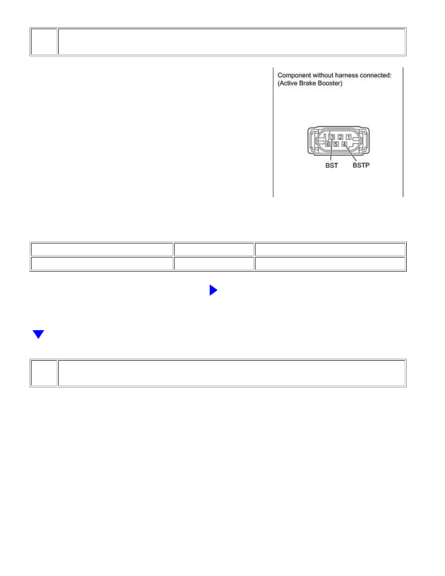
CHECK BRAKE BOOSTER ASSEMBLY

(a) Disconnect the A18 booster connector.

(b) Measure the resistance according to the value(s) in the table below.

Standard Resistance:

TESTER CONNECTION

CONDITION

SPECIFIED CONDITION

3 (BST) - 4 (BSTP)

Always

1.1 to 1.7 Ω

NG

REPLACE BRAKE BOOSTER ASSEMBLY

2.

CHECK HARNESS AND CONNECTOR (SKID CONTROL ECU - ACTIVE BRAKE BOOSTER)

BRAKE CONTROL: VEHICLE STABILITY CONTROL SYSTEM: C...

(a) Confirm that the skid control ECU connector and active brake

booster connector are properly connected.

(b) Disconnect the A17 ECU connector.

(c) Disconnect the A18 booster connector.

(d) Inspect both the connector case and the terminal for deformation and corrosion.

OK:

No deformation or corrosion.

(e) Measure the resistance according to the value(s) in the table below.

Standard Resistance:

TESTER CONNECTION

CONDITION

SPECIFIED CONDITION

A17-31 (BST) - A18-3 (BST)

Always

Below 1 Ω

A17-31 (BST) - Body ground

Always

10 kΩ or higher

A17-17 (BSTP) - A18-4 (BSTP)

Always

Below 1 Ω

A17-17 (BSTP) - Body ground

Always

10 kΩ or higher

NG

REPAIR OR REPLACE HARNESS OR CONNECTOR

OK

REPLACE VSC ACTUATOR ASSEMBLY

BRAKE CONTROL: VEHICLE STABILITY CONTROL SYSTEM: C...

Last Modified: 9-16-2014

6.6 C

Doc ID: RM000001P4P00RX

Model Year: 2015

Model: Tundra

Prod Date Range: [08/2014 -           ]

Title: BRAKE CONTROL: VEHICLE STABILITY CONTROL SYSTEM: C1311/12,C1380/64; Open or Short in Brake

Inhibit Relay Circuit; 2015 MY Tundra [08/2014 -        ]

DTC

C1311/12 Open or Short in Brake Inhibit Relay Circuit

DTC

C1380/64 Stop Light Control Relay Malfunction

DESCRIPTION

The stop light control relays are built into the stop light circuit and prohibits the stop light from turning on under

VSC control.

DTC CODE

DTC DETECTION CONDITION

TROUBLE AREA

C1311/12

Open or short circuit is detected.

Stop light control relay

Stop light control circuit

C1380/64

Open or short circuit is detected.

Stop light control relay

Stop light control circuit

WIRING DIAGRAM

Refer to DTC C1249/49 


.

INSPECTION PROCEDURE

NOTICE:

When replacing the VSC actuator assembly, perform the zero point calibration 


.

PROCEDURE

1.

CHECK TERMINAL VOLTAGE (STOP LIGHT CONTROL RELAY)

BRAKE CONTROL: VEHICLE STABILITY CONTROL SYSTEM: C...

OK

(a) Remove the stop light control relays from the engine room

relay block.

(b) Measure the voltage according to the value(s) in the table below.

Standard Voltage:

TESTER CONNECTION

SWITCH CONDITION

SPECIFIED CONDITION

Stop light control relay terminal 1 (BRK NO. 1) - Body ground

Ignition switch ON

11 to 14 V

Stop light control relay terminal 1 (BRK NO. 2) - Body ground

NG

REPAIR OR REPLACE HARNESS OR CONNECTOR

2.

INSPECT STOP LIGHT CONTROL RELAY (BRK NO. 1, BRK NO. 2)

(a) Remove the stop light control relays (BRK NO. 1 and BRK NO.

2) from the engine room relay block.

(b) Measure the resistance according to the value(s) in the table

below.

Standard Resistance:

for BRK NO. 1

for BRK NO. 2

TESTER

CONNECTION

CONDITION

SPECIFIED

CONDITION

BRAKE CONTROL: VEHICLE STABILITY CONTROL SYSTEM: C...


Content   ..  250  251  252  253   ..