Content .. 2458 2459 2460 2461 ..
Toyota Tundra (2015 year). Manual - part 2460
OK
(a) Reconnect the Z10 position control ECU and switch assembly
connector.
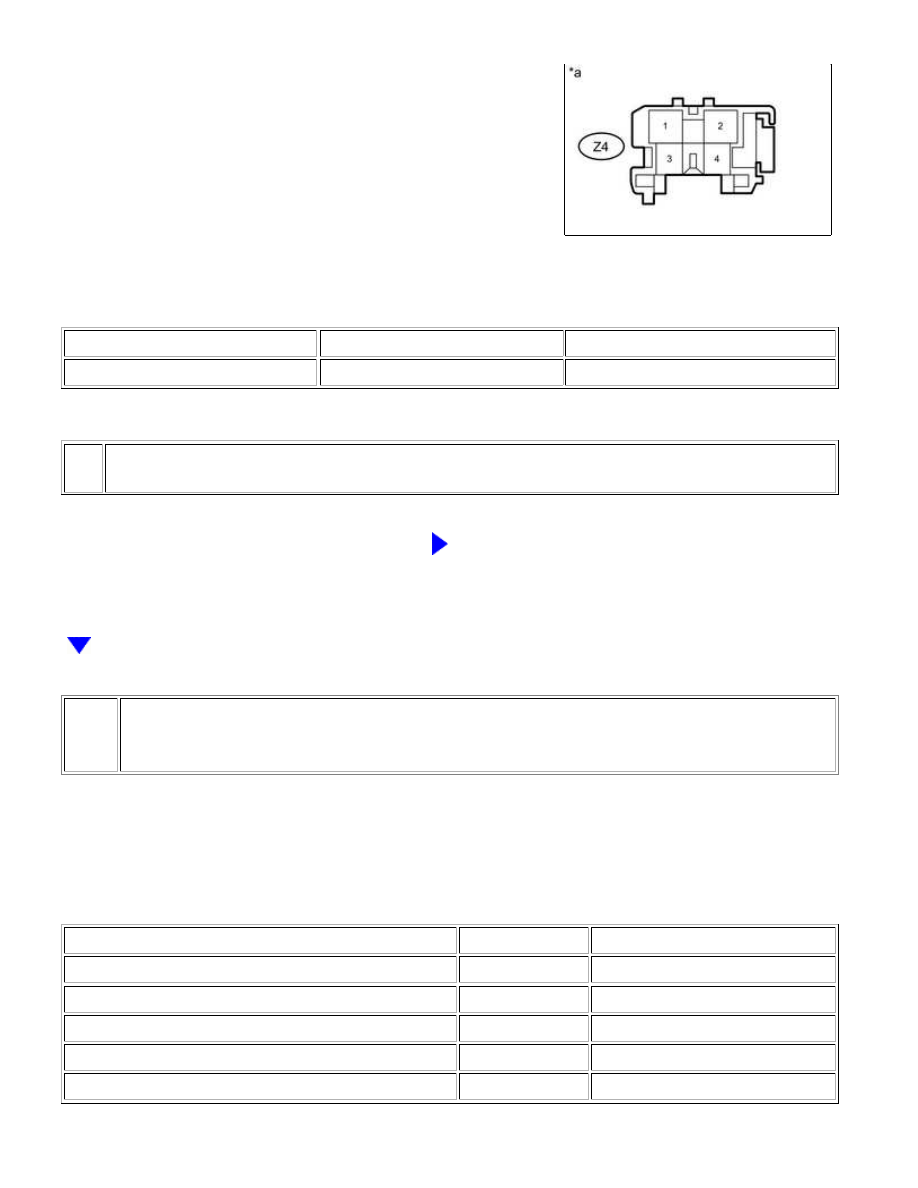
(b) Measure the voltage according to the value(s) in the table below.
Standard Voltage:
TESTER CONNECTION
SWITCH CONDITION
SPECIFIED CONDITION
Z4-4 - Z4-3
Lifter switch on
4.8 to 5.1 V
Text in Illustration
*a
NG
REPLACE POSITION CONTROL ECU AND SWITCH
ASSEMBLY
6.
CHECK HARNESS AND CONNECTOR (POSITION CONTROL ECU AND SWITCH
ASSEMBLY - FRONT SEAT CUSHION FRAME SUB-ASSEMBLY LH)
(a) Disconnect the Z10 position control ECU and switch assembly connector.
(b) Disconnect the Z14 front seat cushion frame sub-assembly LH (vertical motor) connector.
(c) Measure the resistance according to the value(s) in the table below.
Standard Resistance:
TESTER CONNECTION
CONDITION
SPECIFIED CONDITION
Z10-3 (SSFV) - Z14-2
Always
Below 1 Ω
Z10-1 (SGND) - Z14-1
Always
Below 1 Ω
Z10-3 (SSFV) - Z10-1 (SGND)
Always
10 kΩ or higher
Z10-3 (SSFV) or Z14-2 - Body ground
Always
10 kΩ or higher
Z10-1 (SGND) or Z14-1 - Body ground
Always
10 kΩ or higher
SEAT: FRONT POWER SEAT CONTROL SYSTEM (w/ Memory): B265...