Content .. 2351 2352 2353 2354 ..
Toyota Tundra (2015 year). Manual - part 2353
Last Modified: 9-16-2014
6.6 J
Doc ID: RM000001WYB05SX
Model Year: 2015
Model: Tundra
Prod Date Range: [08/2014 - ]
Title: DOOR LOCK: WIRELESS DOOR LOCK CONTROL SYSTEM: Only Wireless Control Function is Inoperative;
2015 MY Tundra [08/2014 - ]
Only Wireless Control Function is Inoperative
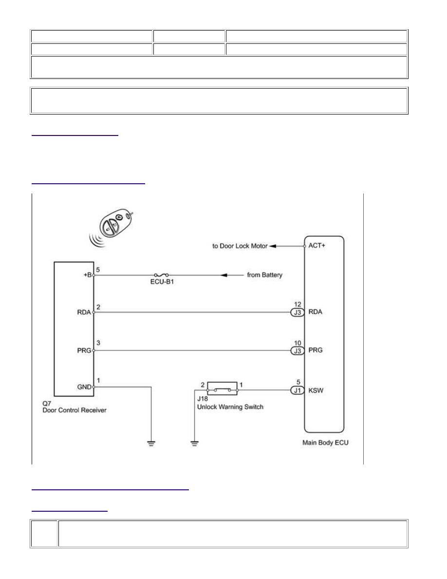
DESCRIPTION
The door control receiver receives signals from the transmitter and sends these signals to the main body ECU. The
main body ECU then controls all doors by sending lock/unlock signals to each door.
WIRING DIAGRAM
INSPECTION PROCEDURE
PROCEDURE
1.
CHECK POWER DOOR LOCK OPERATION FUNCTION
DOOR LOCK: WIRELESS DOOR LOCK CONTROL SYSTEM: Only Wi...