Content .. 2322 2323 2324 2325 ..
Toyota Tundra (2015 year). Manual - part 2324
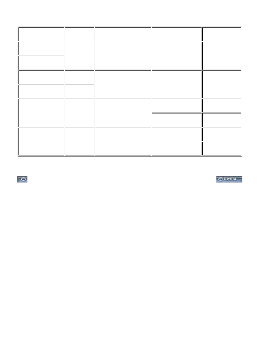
(b) Measure the resistance and voltage according to the value(s) in the table below.
TERMINAL NO.
(SYMBOLS)
WIRING
COLOR
TERMINAL DESCRIPTION
CONDITION
SPECIFIED
CONDITION
DD-21 (GND1) - Body
ground
B - Body
ground
Ground
Always
Below 1 Ω
DD-21 (GND2) - Body
ground
DB-13 (BECU) - Body
ground
GR - Body
ground
Power source
Always
11 to 14 V
DA-1 (ALTB) - Body
ground
B - Body
ground
J4-24 (DCTY) - Body
ground
GR - Body
ground
Front door courtesy switch
LH signal
Switch pushed (Door
closed)
10 kΩ or higher
Switch Not pushed
(Door open)
Below 1 Ω
J1-5 (KSW) - Body
ground
B - Body
ground
Key unlock warning switch
signal
No key is in ignition key
cylinder
10 kΩ or higher
Key is in ignition key
cylinder
Below 1 Ω
HINT:
lf the result is not as specified, the ECU may have a malfunction.
DOOR LOCK: KEY REMINDER WARNING SYSTEM: TERMINALS ...