Toyota Tundra (2015 year). Manual - part 2299


  Index      Toyota     Toyota Tundra (2015 year) - Service and Repair Manual


Search            copyright infringement  


Content   ..  2297  2298  2299  2300   ..


Toyota Tundra (2015 year). Manual - part 2299


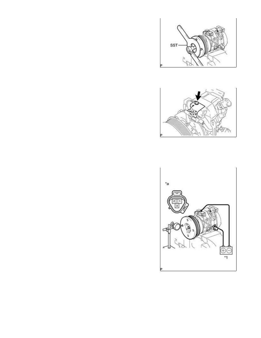
(f) Using SST, hold the magnet clutch hub and install the bolt.

SST: 09985-00270

Torque:

18 N·m {184 kgf·cm, 13ft·lbf}

NOTICE:

Make sure that there is no foreign matter or oil on the

compressor shaft, bolt, and clutch hub.

2. INSTALL COOLER COMPRESSOR BRACKET

(a) Install the cooler compressor bracket with the screw.

(b) Attach the harness clamp.

3. INSPECT MAGNET CLUTCH CLEARANCE

(a) Clamp the cooler compressor assembly in a vise.

(b) Set the dial indicator to the magnet clutch hub.

Standard clearance:

0.35 to 0.60 mm (0.014 to 0.024 in.)

Text in Illustration

AIR CONDITIONING: COMPRESSOR: REASSEMBLY; 2015 MY Tund...

*1

Battery

*a

Component without harness connected

(Magnet Clutch Assembly)

If the measured value is not within the standard clearance, remove the magnet clutch hub and adjust the

clearance using magnet clutch washers to obtain the standard clearance.

Magnet clutch washer thickness:

0.1 mm (0.004 in.)

0.3 mm (0.012 in.)

0.5 mm (0.020 in.)

NOTICE:

Adjustment should be performed with 3 or fewer magnet clutch washers.

(d) Remove the cooler compressor assembly from the vise.

AIR CONDITIONING: COMPRESSOR: REASSEMBLY; 2015 MY Tund...

Last Modified: 9-16-2014

6.6 A

Doc ID: RM0000017ZZ07CX

Model Year: 2015

Model: Tundra

Prod Date Range: [08/2014 -           ]

Title: AIR CONDITIONING: COMPRESSOR: INSTALLATION; 2015 MY Tundra [08/2014 -        ]

INSTALLATION

1. ADJUST COMPRESSOR OIL

(a) When replacing the compressor and magnetic clutch with a new one, gradually discharge the refrigerant

Standard:

(Oil capacity inside the new compressor and magnetic clutch: 120 + 15 cc (4.1 + 0.51 fl. oz.)) - (Remaining

oil amount in the removed compressor and magnetic clutch) = (Oil amount to be removed from the new

compressor when replacing)

NOTICE:

(a) Install the cooler compressor assembly and 2 stud bolts.

Torque:

10 N·m {102 kgf·cm, 7ft·lbf}

(b) Install the 2 bolts and 2 nuts.

Torque:

24.5 N·m {250 kgf·cm, 18ft·lbf}

HINT:

Tighten the bolts and nuts in the order shown in the illustration to install the cooler compressor assembly.

(c) Connect the connector.

3. CONNECT NO. 1 COOLER REFRIGERANT SUCTION HOSE

AIR CONDITIONING: COMPRESSOR: INSTALLATION; 2015 MY Tun...

(a) Remove the attached vinyl tape from the No. 1 cooler

refrigerant suction hose.

ND-OIL 8 or equivalent

(c) Install the O-ring to the No. 1 cooler refrigerant suction hose.

(d) Connect the No. 1 cooler refrigerant suction hose to the cooler compressor assembly with the bolt.

Torque:

9.8 N·m {100 kgf·cm, 87in·lbf}

4. CONNECT NO. 1 COOLER REFRIGERANT DISCHARGE HOSE

(a) Remove the attached vinyl tape from the No. 1 cooler

refrigerant discharge hose.

ND-OIL 8 or equivalent

(c) Install the O-ring to the No. 1 cooler refrigerant discharge hose.

(d) Connect the No. 1 cooler refrigerant discharge hose to the cooler compressor assembly with the bolt.

Torque:

9.8 N·m {100 kgf·cm, 87in·lbf}

5. INSTALL FAN AND GENERATOR V BELT

for 1UR-FE: 

for 3UR-FE: 

for 3UR-FBE: 

6. INSTALL FRONT FENDER APRON SEAL LH

AIR CONDITIONING: COMPRESSOR: INSTALLATION; 2015 MY Tun...


Content   ..  2297  2298  2299  2300   ..