Toyota Tundra (2015 year). Manual - part 2276


  Index      Toyota     Toyota Tundra (2015 year) - Service and Repair Manual


Search            copyright infringement  


Content   ..  2274  2275  2276  2277   ..


Toyota Tundra (2015 year). Manual - part 2276


OK

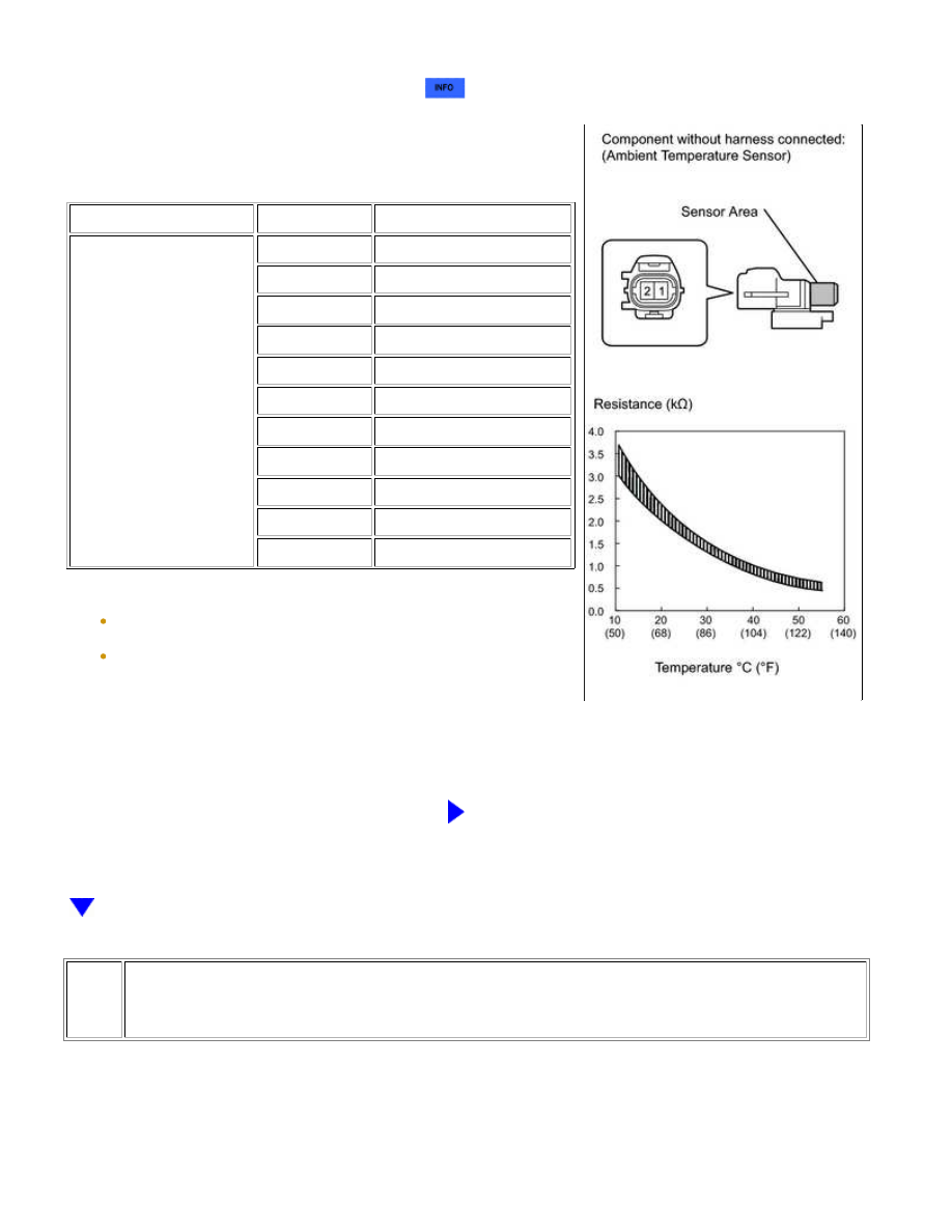
(a) Remove the ambient temperature sensor 


.

(b) Measure the resistance according to the value(s) in the

table below.

Standard resistance:

TESTER CONNECTION

CONDITION

SPECIFIED CONDITION

1 - 2

10°C (50°F)

3.00 to 3.73 kΩ

15°C (59°F)

2.45 to 2.88 kΩ

20°C (68°F)

1.95 to 2.30 kΩ

25°C (77°F)

1.60 to 1.80 kΩ

30°C (86°F)

1.28 to 1.47 kΩ

35°C (95°F)

1.00 to 1.22 kΩ

40°C (104°F)

0.80 to 1.00 kΩ

45°C (113°F)

0.65 to 0.85 kΩ

50°C (122°F)

0.50 to 0.70 kΩ

55°C (131°F)

0.44 to 0.60 kΩ

60°C (140°F)

0.36 to 0.50 kΩ

NOTICE:

As the temperature increases, the resistance decreases (see the

graph).

NG

REPLACE AMBIENT TEMPERATURE SENSOR

3.

CHECK HARNESS AND CONNECTOR (AMBIENT TEMPERATURE SENSOR - AIR
CONDITIONING AMPLIFIER)

AIR CONDITIONING: AIR CONDITIONING SYSTEM (for Manual Air...

(a) Disconnect the A15 sensor connector.

(b) Disconnect the J19 air conditioning amplifier connector.

(c) Measure the resistance according to the value(s) in the table

below.

Standard resistance:

TESTER CONNECTION

CONDITION

SPECIFIED

CONDITION

A15-1 - J19-5 (TAM)

Always

Below 1 Ω

A15-2 - J19-13 (SG-2)

A15-1 or J19-5 (TAM) - Body

ground

Always

10 kΩ or higher

A15-2 or J19-13 (SG-2) - Body

ground

NG

REPAIR OR REPLACE HARNESS OR CONNECTOR

OK

REPLACE AIR CONDITIONING AMPLIFIER

AIR CONDITIONING: AIR CONDITIONING SYSTEM (for Manual Air...

Last Modified: 9-16-2014

6.6 C

Doc ID: RM000002VXD00WX

Model Year: 2015

Model: Tundra

Prod Date Range: [08/2014 -           ]

Title: AIR CONDITIONING: AIR CONDITIONING SYSTEM (for Manual Air Conditioning System): B1413/13;

Evaporator Temperature Sensor Circuit; 2015 MY Tundra [08/2014 -        ]

DTC

B1413/13 Evaporator Temperature Sensor Circuit

DESCRIPTION

The No. 1 cooler thermistor is installed on the evaporator in the air conditioner unit to detect the cooled air

temperature that has passed through the evaporator and control the air conditioning. It sends appropriate signals

increases. As the temperature increases, the resistance decreases.

The air conditioning amplifier applies voltage (5 V) to the No. 1 cooler thermistor and reads voltage changes as

DTC DETECTION CONDITION

TROUBLE AREA

B1413/13

Open or short in evaporator temperature sensor circuit

No. 1 cooler thermistor

Air conditioning harness

Air conditioning amplifier

WIRING DIAGRAM

INSPECTION PROCEDURE

PROCEDURE

AIR CONDITIONING: AIR CONDITIONING SYSTEM (for Manual Air...

A

1.

READ VALUE USING TECHSTREAM (EVAPORATOR FIN THERMISTOR)

(a) Use the Data List to check if the No. 1 cooler thermistor is functioning properly.

Air Conditioner

TESTER DISPLAY

MEASUREMENT ITEM /

RANGE

NORMAL CONDITION

DIAGNOSTIC NOTE

Evaporator Fin

Thermistor

No. 1 cooler thermistor /

Min.: -29.7°C (-21.46°F)

Max.: 59.55°C

(139.19°F)

Actual No. 1 cooler thermistor is

displayed

Open in circuit: -29.7°C

(-21.46°F)

Short in circuit: 59.55°C

(139.19°F)

OK:

The display is as specified in the normal condition.

Result

RESULT

PROCEED TO

NG

A

OK (Checking from the PROBLEM SYMPTOMS TABLE)

B

OK (Checking from the DTC)

C

B

PROCEED TO NEXT CIRCUIT INSPECTION SHOWN IN

PROBLEM SYMPTOMS TABLE

C

REPLACE AIR CONDITIONING AMPLIFIER

2.

INSPECT NO. 1 COOLER THERMISTOR

AIR CONDITIONING: AIR CONDITIONING SYSTEM (for Manual Air...


Content   ..  2274  2275  2276  2277   ..