Toyota Tundra (2015 year). Manual - part 2009


  Index      Toyota     Toyota Tundra (2015 year) - Service and Repair Manual


Search            copyright infringement  


Content   ..  2007  2008  2009  2010   ..


Toyota Tundra (2015 year). Manual - part 2009


Connect the Techstream to the DLC3.

1. 

Turn the ignition switch to ON and turn the Techstream on.

2. 

Clear DTCs (even if no DTCs are stored, perform the clear DTC operation).

3. 

Turn the ignition switch off and wait for at least 30 seconds.

4. 

Turn the ignition switch to ON and turn the Techstream on [A].

5. 

Start the engine.

6. 

Slowly depress the accelerator pedal, raise the engine speed to approximately 3000 rpm for

approximately 5 seconds, and then idle the engine [B].

7. 

Enter the following menus: Powertrain / Engine and ECT / Trouble Codes [C].

8. 

Read the Pending DTCs.

HINT:

If a pending DTC is output, the system is malfunctioning.
If a pending DTC is not output, perform the following procedure.

9. 

Enter the following menus: Powertrain / Engine and ECT / Utility / All Readiness.

10. 

Input the DTC: P2118.

11. 

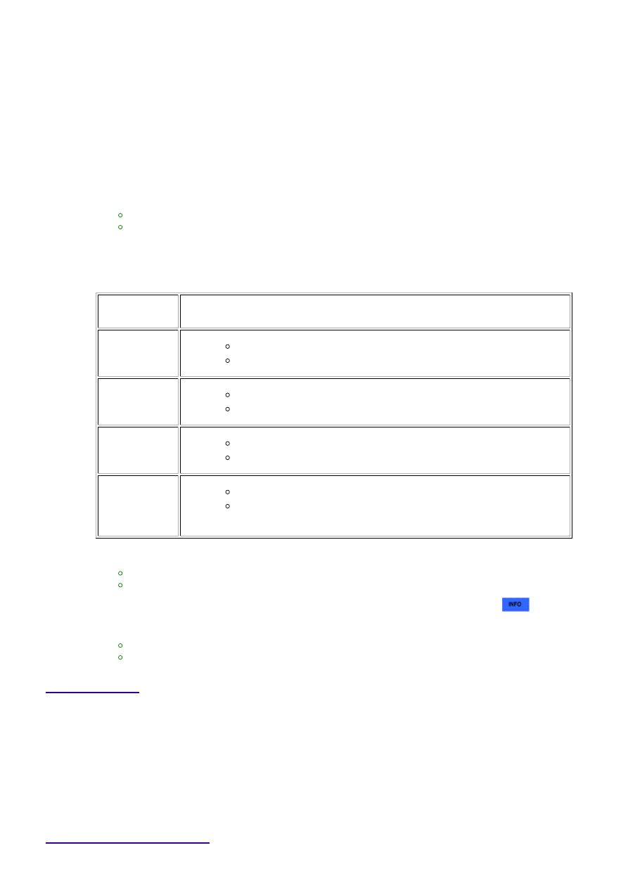
Check the DTC judgment result.

TESTER

DISPLAY

DESCRIPTION

NORMAL

DTC judgment completed

System normal

ABNORMAL

DTC judgment completed

System abnormal

INCOMPLETE

DTC judgment not completed

Perform driving pattern after confirming DTC enabling conditions

N/A

Unable to perform DTC judgment

HINT:

If the judgment result shows ABNORMAL, the system has a malfunction.
If the judgment result shows INCOMPLETE or N/A, perform steps [B] and [C] again.

12. 

If no pending DTC is output, perform a universal trip and check for permanent DTCs 


.

HINT:

If a permanent DTC is output, the system is malfunctioning.
If no permanent DTC is output, the system is normal.

13. 

FAIL-SAFE

When this DTC or other DTCs relating to ETCS (Electronic Throttle Control System) malfunctions are set, the

ECM enters fail-safe mode. During fail-safe mode, the ECM cuts the current to the throttle actuator, and the

throttle valve is returned to a 7° throttle angle by the return spring. The ECM then adjusts the engine output

by controlling the fuel injection (intermittent fuel-cut) and ignition timing, in accordance with the accelerator

pedal opening angle, to allow the vehicle to continue at a minimal speed. If the accelerator pedal is depressed

firmly and gently, the vehicle can be driven slowly.

Fail-safe mode continues until a pass condition is detected, and the ignition switch is then turned OFF.

WIRING DIAGRAM

3UR-FE ENGINE CONTROL SYSTEM: SFI SYSTEM: P2118; Thrott...

INSPECTION PROCEDURE

NOTICE:

Read freeze frame data using the Techstream. Freeze frame data records the engine condition when

malfunctions are detected. When troubleshooting, freeze frame data can help determine if the vehicle
was moving or stationary, if the engine was warmed up or not, if the air-fuel ratio was lean or rich, and
other data from the time the malfunction occurred.

PROCEDURE

1.

READ VALUE USING TECHSTREAM (+BM VOLTAGE)

(a) Connect the Techstream to the DLC3.

(b) Turn the ignition switch to ON.

(c) Turn the Techstream on.

(d) Enter the following menus: Powertrain / Engine and ECT / Data List / All Data / +BM Voltage.

(e) Read the value displayed on the Techstream.

Standard voltage:

11 to 14 V

3UR-FE ENGINE CONTROL SYSTEM: SFI SYSTEM: P2118; Thrott...

NG

GO TO STEP 2

OK

CHECK FOR INTERMITTENT PROBLEMS

2.

CHECK HARNESS AND CONNECTOR (ECM - BATTERY, BODY GROUND)

(a) Disconnect the D74 ECM connector.

(b) Measure the voltage according to the value(s) in the table below.

Standard voltage:

TESTER CONNECTION

CONDITION

SPECIFIED CONDITION

D74-41 (+BM) - Body ground

Always

11 to 14 V

(c) Measure the resistance according to the value(s) in the table below.

Standard Resistance:

TESTER CONNECTION

CONDITION

SPECIFIED CONDITION

D74-82 (ME01) - Body ground

Always

Below 1 Ω

D74-81 (E1) - Body ground

Always

Below 1 Ω

NG

REPAIR OR REPLACE HARNESS OR CONNECTOR

OK

REPLACE ECM

3UR-FE ENGINE CONTROL SYSTEM: SFI SYSTEM: P2118; Thrott...

Last Modified: 9-16-2014

6.6 C

Doc ID: RM000000PFX11UX

Model Year: 2015

Model: Tundra

Prod Date Range: [08/2014 -           ]

Title: 3UR-FE ENGINE CONTROL SYSTEM: SFI SYSTEM: P2119; Throttle Actuator Control Throttle Body

Range / Performance; 2015 MY Tundra [08/2014 -        ]

DTC

P2119

Throttle Actuator Control Throttle Body Range / Performance

DESCRIPTION

DTC

CODE

DTC DETECTION CONDITION

TROUBLE AREA

P2119

Throttle valve opening angle continues to vary greatly from target

opening angle (1 trip detection logic)

ETCS

ECM

Wire harness or

connector

MONITOR DESCRIPTION

these two values is outside the standard range, the ECM interprets this as a malfunction in the ETCS. The ECM

then illuminates the MIL and sets the DTC.

If the malfunction is not repaired successfully, the DTC is set when the accelerator pedal is quickly released (to

close the throttle valve) after the engine speed reaches 5000 rpm by the accelerator pedal being fully

depressed (fully open the throttle valve).

MONITOR STRATEGY

Related DTCs

P2119: ETCS malfunction

Required Sensors/Components (Main)

Throttle actuator

Required Sensors/Components (Related)

-

Duration

Closed: 1 second

Open: 0.6 seconds

MIL Operation

Immediate

TYPICAL ENABLING CONDITIONS

Monitor runs whenever following DTCs not present

None

System guard* judge condition

ON

3UR-FE ENGINE CONTROL SYSTEM: SFI SYSTEM: P2119; Thrott...


Content   ..  2007  2008  2009  2010   ..