Content .. 1992 1993 1994 1995 ..
Toyota Tundra (2015 year). Manual - part 1994
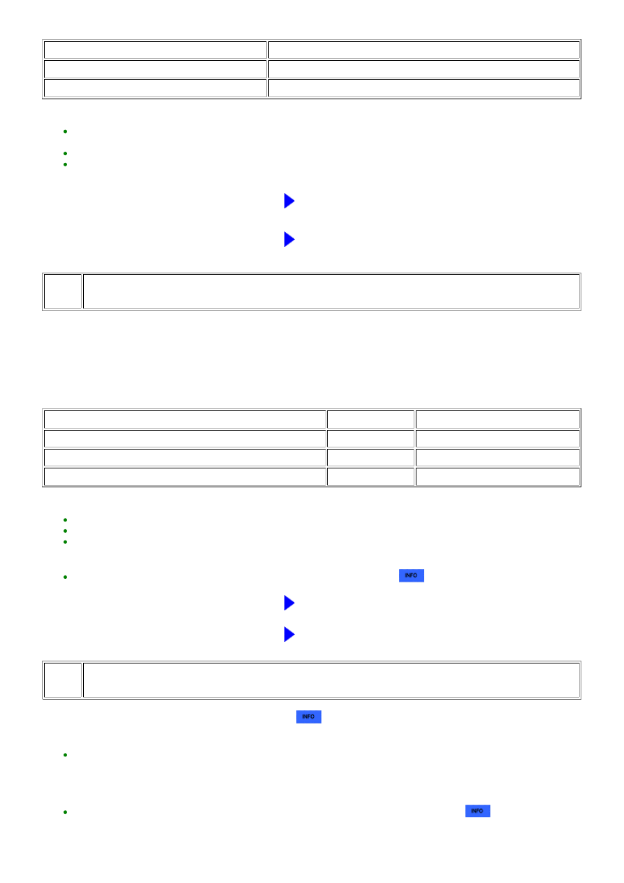
TESTER OPERATION
SPECIFIED CONDITION
0%
Normal engine speed
100%
Engine idles roughly or stalls
HINT:
GO TO STEP 72
NG
REPLACE CAMSHAFT OIL CONTROL VALVE (for Exhaust
Side)
57.
CHECK HARNESS AND CONNECTOR (MASS AIR FLOW METER - ECM)
(a) Disconnect the MAF meter connector.
(b) Disconnect the ECM connector.
(c) Measure the resistance according to the value(s) in the table below.
Standard resistance:
TESTER CONNECTION
CONDITION
SPECIFIED CONDITION
D7-3 (VG) - D74-74 (VG)
Always
Below 1 Ω
D7-2 (E2G) - D74-75 (E2G)
Always
Below 1 Ω
D7-3 (VG) or D74-74 (VG) - Body ground
Always
10 kΩ or higher
HINT:
.
NG
REPAIR OR REPLACE HARNESS OR CONNECTOR
OK
REPLACE MASS AIR FLOW METER
58.
INSPECT ENGINE COOLANT TEMPERATURE SENSOR
(a) Inspect the engine coolant temperature sensor
.
HINT:
If the engine coolant temperature sensor is malfunctioning, after replacing it, check if engine starting trouble
occurs again. If engine starting trouble occurs, replace the ECM. If engine starting trouble still occurs, proceed to
step 72 and perform fuel system troubleshooting A (steps 95 to 102), fuel system troubleshooting B (steps 103 to
105), intake system troubleshooting (steps 106 to 108), and ignition system troubleshooting (steps 109 to 114), in
that order.
Perform "Inspection After Repair" after replacing the engine coolant temperature sensor
.
3UR-FE ENGINE CONTROL SYSTEM: SFI SYSTEM: P1604; Startabi...