Content .. 1991 1992 1993 1994 ..
Toyota Tundra (2015 year). Manual - part 1993
OK
(a) Disconnect the injector connector.
(b) Turn the ignition switch to ON.
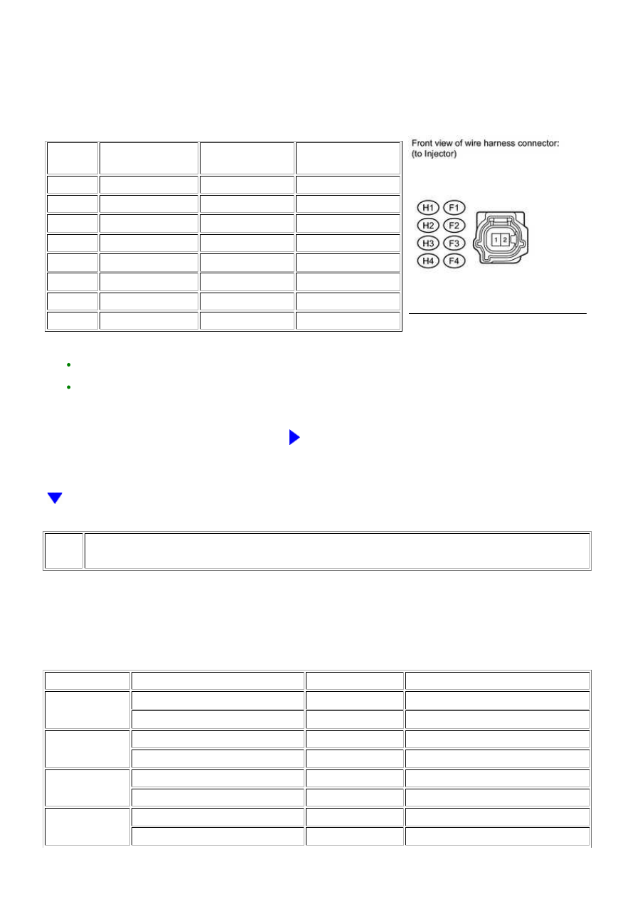
(c) Measure the voltage according to the value(s) in the table below.
Standard voltage:
CYLINDER
TESTER
CONNECTION
SWITCH
CONDITION
SPECIFIED
CONDITION
No. 1
H1-2 - Body ground
Ignition switch ON
11 to 14 V
No. 2
F1-2 - Body ground
Ignition switch ON
11 to 14 V
No. 3
H2-2 - Body ground
Ignition switch ON
11 to 14 V
No. 4
F2-2 - Body ground
Ignition switch ON
11 to 14 V
No. 5
H3-2 - Body ground
Ignition switch ON
11 to 14 V
No. 6
F3-2 - Body ground
Ignition switch ON
11 to 14 V
No. 7
H4-2 - Body ground
Ignition switch ON
11 to 14 V
No. 8
F4-2 - Body ground
Ignition switch ON
11 to 14 V
HINT:
REPAIR POWER SOURCE CIRCUIT
50.
CHECK HARNESS AND CONNECTOR (FUEL INJECTOR - ECM)
(a) Disconnect the injector connector.
(b) Disconnect the ECM connector.
(c) Measure the resistance according to the value(s) in the table below.
Standard resistance:
CYLINDER
TESTER CONNECTION
CONDITION
SPECIFIED CONDITION
No. 1
H1-1 - Body ground
Always
10 kΩ or higher
H1-1 - D74-86 (#10)
Always
Below 1 Ω
No. 2
F1-1 - Body ground
Always
10 kΩ or higher
F1-1 - D74-109 (#20)
Always
Below 1 Ω
No. 3
H2-1 - Body ground
Always
10 kΩ or higher
H2-1 - D74-85 (#30)
Always
Below 1 Ω
No. 4
F2-1 - Body ground
Always
10 kΩ or higher
F2-1 - D74-108 (#40)
Always
Below 1 Ω
3UR-FE ENGINE CONTROL SYSTEM: SFI SYSTEM: P1604; Startabi...