Toyota Tundra (2015 year). Manual - part 1992


  Index      Toyota     Toyota Tundra (2015 year) - Service and Repair Manual


Search            copyright infringement  


Content   ..  1990  1991  1992  1993   ..


Toyota Tundra (2015 year). Manual - part 1992


OK

OK

NG

CHECK CRANKSHAFT POSITION SENSOR CIRCUIT

43.

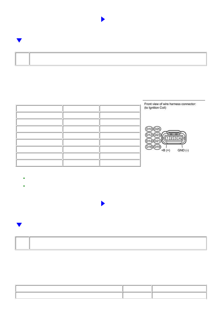
CHECK HARNESS AND CONNECTOR (IGNITION COIL POWER SOURCE)

(a) Disconnect the ignition coil connector.

(b) Turn the ignition switch to ON.

(c) Measure the voltage according to the value(s) in the table below.

Standard voltage:

TESTER CONNECTION

SWITCH CONDITION

SPECIFIED CONDITION

D10-1 (+B) - D10-4 (GND)

Ignition switch ON

11 to 14 V

D25-1 (+B) - D25-4 (GND)

Ignition switch ON

11 to 14 V

D12-1 (+B) - D12-4 (GND)

Ignition switch ON

11 to 14 V

D23-1 (+B) - D23-4 (GND)

Ignition switch ON

11 to 14 V

D14-1 (+B) - D14-4 (GND)

Ignition switch ON

11 to 14 V

D21-1 (+B) - D21-4 (GND)

Ignition switch ON

11 to 14 V

D16-1 (+B) - D16-4 (GND)

Ignition switch ON

11 to 14 V

D19-1 (+B) - D19-4 (GND)

Ignition switch ON

11 to 14 V

HINT:

CHECK POWER SOURCE CIRCUIT

44.

CHECK HARNESS AND CONNECTOR (IGNITION COIL - ECM)

(a) Disconnect the ignition coil connector.

(b) Disconnect the ECM connector.

(c) Measure the resistance according to the value(s) in the table below.

Standard resistance:

TESTER CONNECTION

CONDITION

SPECIFIED CONDITION

D10-2 (IGF1) - D74-104 (IGF1)

Always

Below 1 Ω

3UR-FE ENGINE CONTROL SYSTEM: SFI SYSTEM: P1604; Startabi...

OK

TESTER CONNECTION

CONDITION

SPECIFIED CONDITION

D25-2 (IGF2) - D74-105 (IGF2)

Always

Below 1 Ω

D12-2 (IGF2) - D74-105 (IGF2)

Always

Below 1 Ω

D23-2 (IGF1) - D74-104 (IGF1)

Always

Below 1 Ω

D14-2 (IGF2) - D74-105 (IGF2)

Always

Below 1 Ω

D21-2 (IGF1) - D74-104 (IGF1)

Always

Below 1 Ω

D16-2 (IGF1) - D74-104 (IGF1)

Always

Below 1 Ω

D19-2 (IGF2) - D74-105 (IGF2)

Always

Below 1 Ω

D10-2 (IGF1) or D74-104 (IGF1) - Body ground

Always

10 kΩ or higher

D25-2 (IGF2) or D74-105 (IGF2) - Body ground

Always

10 kΩ or higher

D12-2 (IGF2) or D74-105 (IGF2) - Body ground

Always

10 kΩ or higher

D23-2 (IGF1) or D74-104 (IGF1) - Body ground

Always

10 kΩ or higher

D14-2 (IGF2) or D74-105 (IGF2) - Body ground

Always

10 kΩ or higher

D21-2 (IGF1) or D74-104 (IGF1) - Body ground

Always

10 kΩ or higher

D16-2 (IGF1) or D74-104 (IGF1) - Body ground

Always

10 kΩ or higher

D19-2 (IGF2) or D74-105 (IGF2) - Body ground

Always

10 kΩ or higher

HINT:

REPAIR OR REPLACE HARNESS OR CONNECTOR

45.

CHECK HARNESS AND CONNECTOR (IGNITION COIL - ECM)

(a) Disconnect the ignition coil connector.

(b) Disconnect the ECM connector.

(c) Measure the resistance according to the value(s) in the table below.

Standard resistance:

TESTER CONNECTION

CONDITION

SPECIFIED CONDITION

D10-3 (IGT1) - D74-40 (IGT1)

Always

Below 1 Ω

D25-3 (IGT2) - D74-33 (IGT2)

Always

Below 1 Ω

D12-3 (IGT3) - D74-37 (IGT3)

Always

Below 1 Ω

D23-3 (IGT4) - D74-34 (IGT4)

Always

Below 1 Ω

D14-3 (IGT5) - D74-35 (IGT5)

Always

Below 1 Ω

D21-3 (IGT6) - D74-36 (IGT6)

Always

Below 1 Ω

D16-3 (IGT7) - D74-38 (IGT7)

Always

Below 1 Ω

D19-3 (IGT8) - D74-39 (IGT8)

Always

Below 1 Ω

D10-3 (IGT1) or D74-40 (IGT1) - Body ground

Always

10 kΩ or higher

3UR-FE ENGINE CONTROL SYSTEM: SFI SYSTEM: P1604; Startabi...

OK

TESTER CONNECTION

CONDITION

SPECIFIED CONDITION

D25-3 (IGT2) or D74-33 (IGT2) - Body ground

Always

10 kΩ or higher

D12-3 (IGT3) or D74-37 (IGT3) - Body ground

Always

10 kΩ or higher

D23-3 (IGT4) or D74-34 (IGT4) - Body ground

Always

10 kΩ or higher

D14-3 (IGT5) or D74-35 (IGT5) - Body ground

Always

10 kΩ or higher

D21-3 (IGT6) or D74-36 (IGT6) - Body ground

Always

10 kΩ or higher

D16-3 (IGT7) or D74-38 (IGT7) - Body ground

Always

10 kΩ or higher

D19-3 (IGT8) or D74-39 (IGT8) - Body ground

Always

10 kΩ or higher

HINT:


.

NG

REPAIR OR REPLACE HARNESS OR CONNECTOR

OK

REPLACE IGNITION COIL

46.

PERFORM ACTIVE TEST USING TECHSTREAM (CONTROL THE FUEL PUMP / SPEED)

(a) Connect the Techstream to the DLC3.

(b) Turn the ignition switch to ON.

(c) Using the Techstream, select the [Control the Fuel Pump / Speed] Active Test.

(d) When performing the Active Test, check for an operating sound from the fuel pump.

Standard:

CONTROL THE FUEL PUMP / SPEED

SPECIFIED CONDITION

ON

Operating sound heard

OFF

Operating sound not heard

HINT:

CHECK FUEL PUMP CONTROL SYSTEM

47.

PERFORM ACTIVE TEST USING TECHSTREAM (CONTROL THE FUEL PUMP / SPEED)

(a) Connect the Techstream to the DLC3.

(b) Turn the ignition switch to ON.

3UR-FE ENGINE CONTROL SYSTEM: SFI SYSTEM: P1604; Startabi...

OK

(c) Using the Techstream, select the [Control the Fuel Pump / Speed] Active Test.

(d) When performing the Active Test, check for fuel leakage from the fuel pipes.

Result

RESULT

PROCEED TO

HINT:

CHECK FUEL PUMP CONTROL SYSTEM

A

REPAIR OR REPLACE FUEL LINE

48.

READ VALUE USING TECHSTREAM (ENGINE SPEED)

(a) Connect the Techstream to the DLC3.

(b) Turn the ignition switch to ON.

(e) While running the engine, read the [Engine Speed] value.

Standard:

A value that matches the actual engine speed is constantly output.

HINT:

Check the engine speed using a line graph.
If the engine cannot be started, check the engine speed while cranking the engine.
If the engine speed is 0 rpm, the crankshaft position sensor may have an open or short circuit.

NG

REPLACE CRANKSHAFT POSITION SENSOR

49.

CHECK HARNESS AND CONNECTOR (FUEL INJECTOR POWER SOURCE)

3UR-FE ENGINE CONTROL SYSTEM: SFI SYSTEM: P1604; Startabi...


Content   ..  1990  1991  1992  1993   ..