Toyota Tundra (2015 year). Manual - part 1981


  Index      Toyota     Toyota Tundra (2015 year) - Service and Repair Manual


Search            copyright infringement  


Content   ..  1979  1980  1981  1982   ..


Toyota Tundra (2015 year). Manual - part 1981


OK

OK

(b) Disconnect the engine coolant temperature sensor connector.

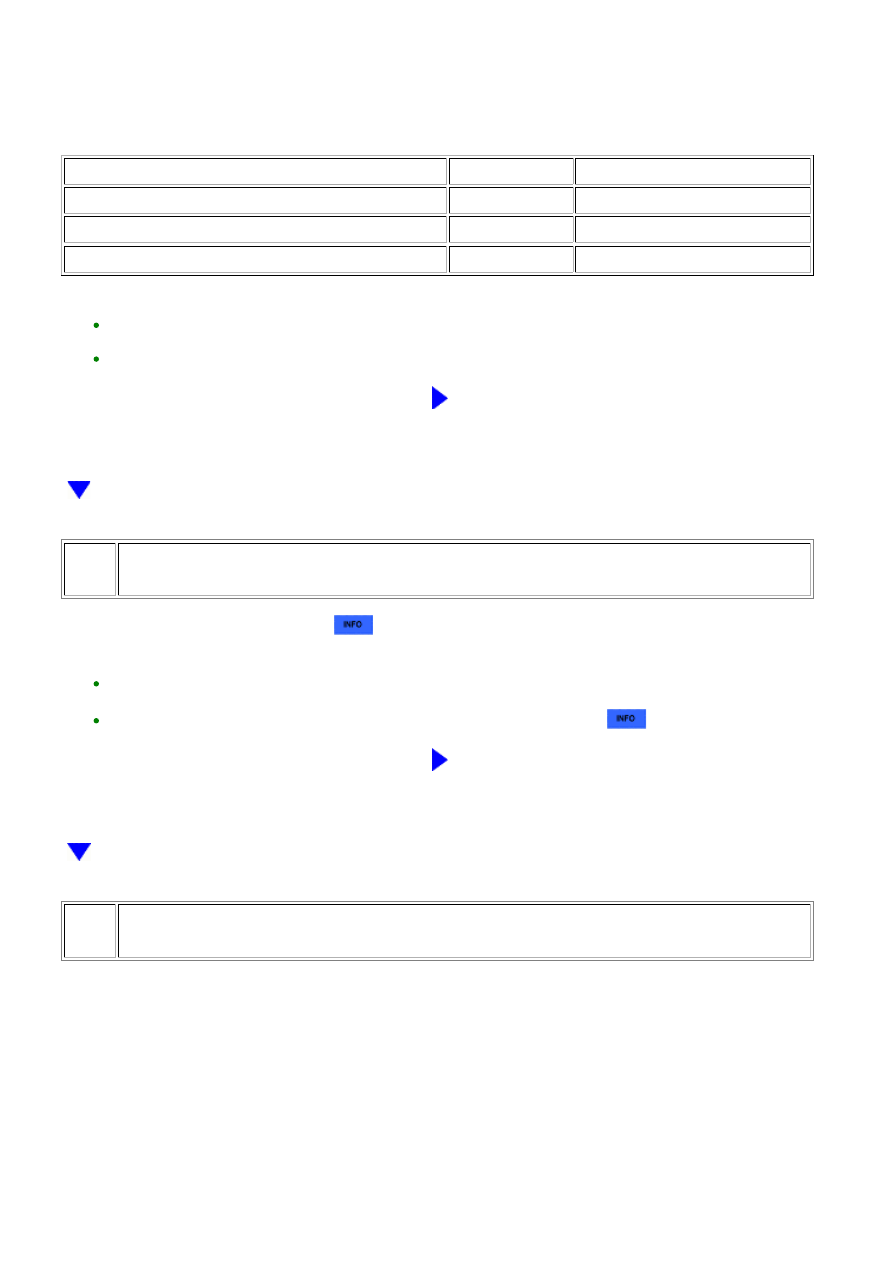
(c) Measure the resistance according to the value(s) in the table below.

Standard Resistance:

TESTER CONNECTION

CONDITION

SPECIFIED CONDITION

D74-76 (THW) - D28-2

Always

Below 1 Ω

D74-98 (ETHA) - D28-1

Always

Below 1 Ω

D74-76 (THW) or D28-2 - Body ground

Always

10 kΩ or higher

HINT:

REPAIR OR REPLACE HARNESS OR CONNECTOR

63.

INSPECT MASS AIR FLOW METER (INTAKE AIR TEMPERATURE SENSOR)

(a) Inspect the mass air flow meter 


.

HINT:

If the intake air temperature sent to the ECM is higher than the standard due to the mass air flow meter
(intake air temperature sensor) malfunctioning, the ignition timing may become delayed.

Perform "Inspection After Repair" after replacing the mass air flow meter 


.

NG

REPLACE MASS AIR FLOW METER

64.

READ VALUE USING TECHSTREAM

(a) Connect the Techstream to the DLC3.

(b) Start the engine and warm it up until the engine coolant temperature stabilizes.

HINT:

The A/C switch and all accessory switches should be off.

(c) Idle the engine.

Result

3UR-FE ENGINE CONTROL SYSTEM: SFI SYSTEM: P1603,P1605;...

FREEZE FRAME DATA ITEM FOR DTC P1605

PROCEED TO

IGN ADVANCE

KNOCK CORRECT LEARN VALUE

A

3° or more

B

HINT:

B

END

A

CHECK KNOCK SENSOR CIRCUIT

65.

CHECK TERMINAL VOLTAGE (FUEL INJECTOR POWER SOURCE)

(a) Disconnect the fuel injector assembly connectors.

(b) Turn the ignition switch to ON.

(c) Measure the voltage according to the value(s) in the table below.

Standard Voltage:

CYLINDER

TESTER CONNECTION

SWITCH CONDITION

SPECIFIED CONDITION

No. 1

H1-2 - Body ground

Ignition switch ON

11 to 14 V

No. 2

F1-2 - Body ground

Ignition switch ON

11 to 14 V

No. 3

H2-2 - Body ground

Ignition switch ON

11 to 14 V

No. 4

F2-2 - Body ground

Ignition switch ON

11 to 14 V

No. 5

H3-2 - Body ground

Ignition switch ON

11 to 14 V

No. 6

F3-2 - Body ground

Ignition switch ON

11 to 14 V

No. 7

H4-2 - Body ground

Ignition switch ON

11 to 14 V

No. 8

F4-2 - Body ground

Ignition switch ON

11 to 14 V

3UR-FE ENGINE CONTROL SYSTEM: SFI SYSTEM: P1603,P1605;...

OK

OK

HINT:

REPAIR FUEL INJECTOR POWER SOURCE

CIRCUIT

66.

CHECK IGNITION SYSTEM

(a) Perform ignition system On-vehicle Inspection 


.

HINT:

Perform "Inspection After Repair" after repairing or replacing the ignition system 


.

NG

REPAIR OR REPLACE MALFUNCTIONING PARTS,

COMPONENT AND AREA

67.

CHECK FREEZE FRAME DATA

(a) Connect the Techstream to the DLC3.

(b) Turn the ignition switch to ON.

(c) Using the Techstream, confirm the vehicle conditions recorded in the freeze frame data which

were present when the DTC was stored 


.

Result

FREEZE FRAME DATA ITEM FOR DTC P1605

SUSPECTED

AREA

PROCEED

TO

A/C SIGNAL

AIR CONDITIONER FB VAL

POWER

STEERING

SIGNAL

A/C Signal display does

not change from OFF*

-

Does not change

from OFF

-

A

Changes from

OFF to ON

Power steering

system

A/C Signal display

changes from OFF to

Value displayed for Air

Conditioner FB Val does not

Changes from

OFF to ON

3UR-FE ENGINE CONTROL SYSTEM: SFI SYSTEM: P1603,P1605;...

A

FREEZE FRAME DATA ITEM FOR DTC P1605

SUSPECTED

AREA

PROCEED

TO

A/C SIGNAL

AIR CONDITIONER FB VAL

POWER

STEERING

SIGNAL

ON*

increase

Does not change

from OFF

-

Value displayed for Air

Conditioner FB Val increases

-

A/C system

B

HINT:

CHECK AIR CONDITIONING SYSTEM

68.

CHECK FREEZE FRAME DATA

(a) Connect the Techstream to the DLC3.

(b) Turn the ignition switch to ON.

(c) Using the Techstream, confirm the vehicle conditions recorded in the freeze frame data which

were present when the DTC was stored 


.

Result

FREEZE FRAME DATA ITEM FOR DTC P1605

SUSPECTED

AREA

PROCEED

TO

ELECTRICAL LOAD SIGNAL

OR ELECTRIC LOAD

FEEDBACK VAL

ELECTRIC LOAD

FEEDBACK VAL

DIFFERENCE

BETWEEN ENGINE

SPEED AND SPD

(NT)

VEHICLE

SPEED

Electrical Load Signal display

changes from OFF to ON*3,

or value displayed for Electric

Load Feedback Val increases*

Value displayed

for Electric Load

Val changes

-

-

Electrical load

signal circuit

C

Value displayed

for Electric Load

Val does not

change

data is less than 100

rpm

Less than

30 km/h

A/T system

B

30 km/h

or more

-

A

rpm or more

-

-

A

Electrical Load Signal display

does not change from OFF, or

-

Less than

30 km/h

A/T system

B

3UR-FE ENGINE CONTROL SYSTEM: SFI SYSTEM: P1603,P1605;...


Content   ..  1979  1980  1981  1982   ..