Content .. 1980 1981 1982 1983 ..
Toyota Tundra (2015 year). Manual - part 1982
A
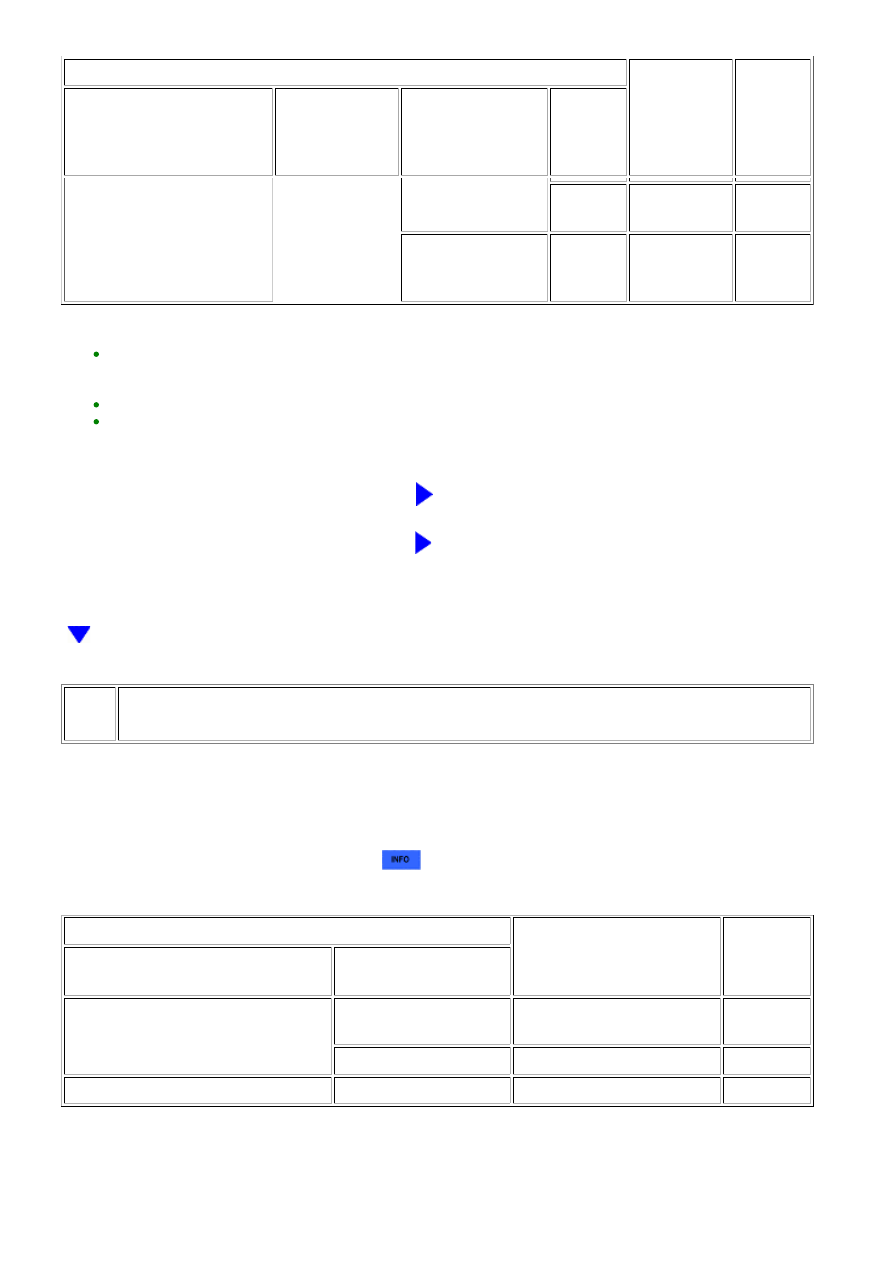
FREEZE FRAME DATA ITEM FOR DTC P1605
SUSPECTED
AREA
PROCEED
TO
ELECTRICAL LOAD SIGNAL
OR ELECTRIC LOAD
FEEDBACK VAL
ELECTRIC LOAD
FEEDBACK VAL
DIFFERENCE
BETWEEN ENGINE
SPEED AND SPD
(NT)
VEHICLE
SPEED
value displayed for Electric
Load Feedback Val does not
increase
data is less than 100
rpm
30 km/h
or more
-
A
rpm or more
-
-
A
HINT:
*: If the Electrical Load Signal display changes from OFF to ON, or the "Electric Load Feedback Val"
increases, it probably is a malfunction due to a change in electrical load. Check the generator and the
continuity and connections between the generator and ECM.
The normal value for the ISC learned value is engine displacement (liters) x 0.9.
Even if the results are normal, the electrical load signal system and/or A/T system may have been
malfunctioning. If there are no problems with other parts, inspect the electrical load system and/or A/T
system.
B
CHECK AUTOMATIC TRANSMISSION SYSTEM
C
CHECK GENERATOR CIRCUIT
69.
CHECK FREEZE FRAME DATA
(a) Connect the Techstream to the DLC3.
(b) Turn the ignition switch to ON.
(c) Using the Techstream, confirm the vehicle conditions recorded in the freeze frame data which
were present when the DTC was stored
.
Result
FREEZE FRAME DATA ITEM FOR DTC P1605
SUSPECTED AREA
PROCEED
TO
SHIFT SW STATUS (P RANGE)
SHIFT SW STATUS (N RANGE)
NEUTRAL POSITION SW
SIGNAL
P and N position are both OFF in at
least one data set
In D or R, NSW is ON
Park/neutral position switch
assembly
A
In D or R, NSW is OFF
A/T system
B
-
C
HINT:
Even if the results are normal, the park/neutral position switch assembly and/or A/T system may have
been malfunctioning. If there are no problems with other parts, inspect the park/neutral position switch
assembly and/or A/T system.
3UR-FE ENGINE CONTROL SYSTEM: SFI SYSTEM: P1603,P1605;...