Content .. 1971 1972 1973 1974 ..
Toyota Tundra (2015 year). Manual - part 1973
PROBLEM SYMPTOM
FREEZE FRAME DATA ITEM FOR DTC P1605
SUSPECTED AREA
PROCEED
TO
CLOSED
THROTTLE
POSITION SW
ENGINE
SPEED
TOTAL OF
SHORT FT AND
LONG FT
problem
At least 1 of
the 5 sets of
freeze frame
data is -15% or
less*3
Sensor malfunction (value
from sensor too rich)
B
All 5 sets of
freeze frame
data are from
-15% to +15%
Intake air
volume
insufficient
Ignition timing
incorrect
C
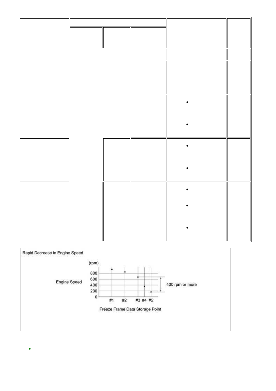
When idling or
decelerating, engine
speed rapidly
decreases and engine
stalls
Decreases
rapidly*1
-
Injection
stoppage,
ignition stoppage
Load from
external parts
D
When accelerating or
driving at constant
speed, engine stalls*4
At least one is
OFF
-
-
Sensor
malfunction
Injection
stoppage,
ignition stoppage
Fuel supply
problem
E
HINT:
3UR-FE ENGINE CONTROL SYSTEM: SFI SYSTEM: P1603,P1605;...