Toyota Tundra (2015 year). Manual - part 1970


  Index      Toyota     Toyota Tundra (2015 year) - Service and Repair Manual


Search            copyright infringement  


Content   ..  1968  1969  1970  1971   ..


Toyota Tundra (2015 year). Manual - part 1970


OK

OK

PROCEDURE

1.

INSPECT AIR PUMP HEATER RELAY

(a) Inspect the air pump heater relay 


.

NG

REPLACE AIR PUMP HEATER RELAY

2.

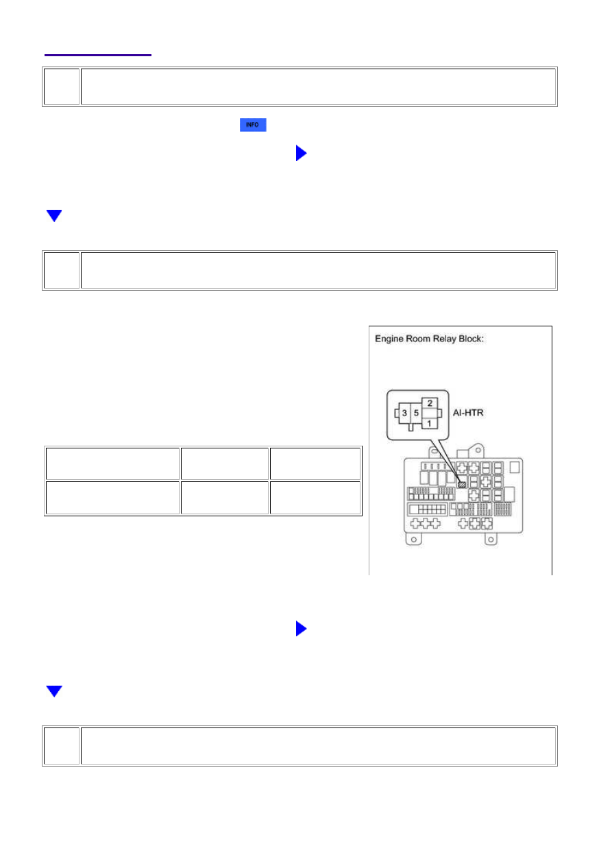
CHECK AIR PUMP HEATER RELAY (POWER SOURCE)

(a) Remove the air pump heater relay (AI-HTR).

(b) Measure the voltage according to the value(s) in the

table below.

Standard Voltage:

TESTER CONNECTION

CONDITION

SPECIFIED

CONDITION

AI-HTR relay terminal 1 -

Body ground

Ignition switch on

(IG)

11 to 14 V

(c) Reinstall the air pump heater relay (AI-HTR).

NG

REPAIR OR REPLACE HARNESS OR CONNECTOR

3.

CHECK HARNESS AND CONNECTOR (ECM - AIR PUMP HEATER RELAY)

(a) Remove the air pump heater relay (AI-HTR).

(b) Disconnect the ECM connector.

3UR-FE ENGINE CONTROL SYSTEM: SFI SYSTEM: P144C,P144D...

(c) Measure the resistance according to the value(s) in the table below.

Standard Resistance (Check for Open):

TESTER CONNECTION

CONDITION

SPECIFIED CONDITION

AI-HTR relay terminal 2 - D74-61 (HAI1)

Always

Below 1 Ω

Standard Resistance (Check for Short):

TESTER CONNECTION

CONDITION

SPECIFIED CONDITION

AI-HTR relay terminal 2 or D74-61 (HAI1) - Body ground

Always

10 kΩ or higher

(d) Reinstall the air pump heater relay (AI-HTR).

(e) Reconnect the ECM connector.

NG

REPAIR OR REPLACE HARNESS OR CONNECTOR

OK

REPLACE ECM

3UR-FE ENGINE CONTROL SYSTEM: SFI SYSTEM: P144C,P144D...

Last Modified: 9-16-2014

6.6 C

Doc ID: RM0000021140P6X

Model Year: 2015

Model: Tundra

Prod Date Range: [08/2014 -           ]

Title: 3UR-FE ENGINE CONTROL SYSTEM: SFI SYSTEM: P1603,P1605; Engine Stall History; 2015 MY Tundra

[08/2014 -        ]

DTC

P1603

Engine Stall History

DTC

P1605

Rough Idling

DESCRIPTION

P1603

After starting the engine, this DTC is stored when the engine stops without the ignition switch being operated.

Using the Techstream, the conditions present when the DTC was stored can be confirmed by referring to the

freeze frame data. Freeze frame data records engine conditions when a malfunction occurs. This information

can be useful when troubleshooting.

DTC

NO.

DTC DETECTION CONDITION

TROUBLE AREA

P1603

After monitoring for startability problems (P1604) finishes

and 5 seconds or more elapse after starting the engine, with

the engine running, the engine stops (the engine speed drops

to 200 rpm or less) without the ignition switch being

operated for 0.5 seconds or more (1 trip detection logic).

Air leak in intake system

Purge VSV

Brake booster

Mass air flow meter

Engine coolant temperature

sensor

Thermostat

Power supply circuit (purge

VSV, air fuel ratio sensor,

fuel injector assembly,

ignition coil assembly)

Fuel pump

Fuel pump control circuit

Fuel line

PCV valve and hose

Camshaft timing oil control

valve

Knock sensor

Ignition system

Air conditioning system

Power steering system

Electrical load signal system

Charging system

A/T system

Park/neutral position switch

assembly

ECM

3UR-FE ENGINE CONTROL SYSTEM: SFI SYSTEM: P1603,P1605;...

DTC

NO.

DTC DETECTION CONDITION

TROUBLE AREA

Wire harness or connector

Engine immobiliser system

P1605

This DTC is stored if the engine speed drops below the set speed without the ignition switch being operated.

Using the Techstream, the conditions present when the DTC was stored can be confirmed by referring to the

freeze frame data. Freeze frame data records engine conditions when a malfunction occurs. This information

can be useful when troubleshooting.

DTC

NO.

DTC DETECTION CONDITION

TROUBLE AREA

P1605

After 5 seconds or more elapse after starting the

engine, with the engine running, the engine speed

drops to 400 rpm or less without the ignition switch

being operated (1 trip detection logic).

Air leak in intake system

Purge VSV

Brake booster

Mass air flow meter

Engine coolant temperature

sensor

Thermostat

Power supply circuit (purge VSV,

air fuel ratio sensor, fuel injector

assembly, ignition coil assembly)

Fuel pump

Fuel pump control circuit

Fuel line

PCV valve and hose

Camshaft timing oil control valve

Knock sensor

Ignition system

Air conditioning system

Power steering system

Electrical load signal system

Charging system

A/T system

Park/neutral position switch

assembly

ECM

Wire harness or connector

Engine immobiliser system

INSPECTION PROCEDURE

HINT:

In contrast to normal malfunction diagnosis for components, circuits and systems, DTCs P1603 and
P1605 are used to determine the malfunctioning area from the problem symptoms and freeze frame
data when the user mentions problems such as engine stall.

3UR-FE ENGINE CONTROL SYSTEM: SFI SYSTEM: P1603,P1605;...


Content   ..  1968  1969  1970  1971   ..