Toyota Tundra (2015 year). Manual - part 1929


  Index      Toyota     Toyota Tundra (2015 year) - Service and Repair Manual


Search            copyright infringement  


Content   ..  1927  1928  1929  1930   ..


Toyota Tundra (2015 year). Manual - part 1929


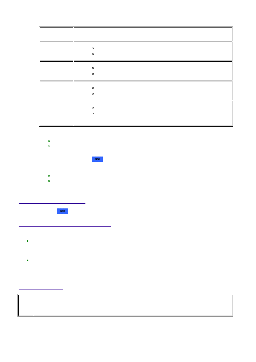
Check the DTC judgment result.

TESTER

DISPLAY

DESCRIPTION

NORMAL

DTC judgment completed

System normal

ABNORMAL

DTC judgment completed

System abnormal

INCOMPLETE

DTC judgment not completed

Perform driving pattern after confirming DTC enabling conditions

N/A

Unable to perform DTC judgment

HINT:

If the judgment result shows NORMAL, the system is normal.
If the judgment result shows ABNORMAL, the system has a malfunction.

16. 

If the test result is INCOMPLETE or N/A and no pending DTC is output, perform a universal trip and

check for permanent DTCs 


.

HINT:

If no permanent DTC is output, the system is normal.
If a permanent DTC is output, the system is malfunctioning.

17. 

Turn the ignition switch off.

18. 

WIRING DIAGRAM

Refer to DTC P0412 


.

INSPECTION PROCEDURE

HINT:

By using the Techstream to perform the Air Injection Check operation in the System Check, the air-fuel
ratio and the pressure in the secondary air injection system passage can be checked while the
secondary air injection system is operating. This helps technicians to troubleshoot the system when it
malfunctions.
Read freeze frame data using the Techstream. Freeze frame data records the engine condition when
malfunctions are detected. When troubleshooting, freeze frame data can help determine if the vehicle
was moving or stationary, if the engine was warmed up or not, if the air-fuel ratio was lean or rich, and
other data from the time the malfunction occurred.

PROCEDURE

1.

CHECK HARNESS AND CONNECTOR (AIR PUMP - AIR INJECTION CONTROL
DRIVER, BODY GROUND)

(a) Disconnect the cable from the battery negative (-) terminal.

(b) Disconnect the cable from the battery positive (+) terminal.

3UR-FE ENGINE CONTROL SYSTEM: SFI SYSTEM: P0418,P0419;...

OK

(c) Disconnect the air pump connector.

(d) Disconnect the AID connector.

(e) Measure the resistance according to the value(s) in the table below.

Standard Resistance:

TESTER CONNECTION

CONDITION

SPECIFIED CONDITION

D89-2 (B) - D48-2 (VP)

Always

Below 1 Ω

D90-2 (+B) - D52-2 (VP2)

Always

Below 1 Ω

D48-1 (BATT) - Battery positive (+) terminal

Always

Below 1 Ω

D52-1 (BAT2) - Battery positive (+) terminal

Always

Below 1 Ω

D89-4 (E) - Body ground

Always

Below 1 Ω

D90-4 (GND) - Body ground

Always

Below 1 Ω

D89-2 (B) or D48-2 (VP) - Body ground

Always

10 kΩ or higher

D90-2 (+B) or D52-2 (VP2) - Body ground

Always

10 kΩ or higher

D48-1 (BATT) or Battery positive (+) terminal - Body ground

Always

10 kΩ or higher

D52-1 (BAT2) or Battery positive (+) terminal - Body ground

Always

10 kΩ or higher

NG

REPAIR OR REPLACE HARNESS OR CONNECTOR

2.

INSPECT AIR PUMP ASSEMBLY

(a) Start the engine and warm it up.

(b) Turn the ignition switch off.

(e) Turn the ignition switch to ON and turn the Techstream on.

3UR-FE ENGINE CONTROL SYSTEM: SFI SYSTEM: P0418,P0419;...

NEXT

(f) Start the engine.

(g) Enter the following menus: Powertrain / Engine and ECT / Utility / Air Injection Check /

Manual Mode / AIR PUMP 1: ON, ASV1: OPEN, AIR PUMP 2: ON, ASV2: OPEN and AIR PUMP 1:
OFF, ASV1: CLOSE, AIR PUMP 2: OFF, ASV2: CLOSE.

HINT:

When Manual Mode is selected, the Techstream initialization (atmospheric pressure measurement) is

performed automatically. The initialization takes 10 seconds. After the initialization, AIR PUMP and ASV
operation can be selected.

(h) Measure the current while the air pump is on and off.

Standard Current:

TESTER OPERATION

AIR PUMP

ASV

SPECIFIED CONDITION

AIR PUMP: ON, ASV: OPEN

ON

OPEN

10 to 40 A

AIR PUMP: OFF, ASV: CLOSE

OFF

CLOSE

Below 1 A

NOTICE:

the prohibition (WAIT or ERROR).

If ERROR is displayed on the Techstream during the test, stop the engine for 10 minutes, and then

try again.

GO TO STEP 3

OK

REPLACE AIR INJECTION CONTROL DRIVER

3.

REPLACE AIR PUMP ASSEMBLY

(a) Replace the air pump assembly 


.

4.

CHECK WHETHER DTC OUTPUT RECURS

(a) Start the engine and warm it up.

(b) Turn the ignition switch off.

3UR-FE ENGINE CONTROL SYSTEM: SFI SYSTEM: P0418,P0419;...

(c) Connect the Techstream to the DLC3.

(d) Turn the ignition switch to ON and turn the Techstream on.

(e) Clear DTCs (if set) 


.

(f) Enter the following menus: Powertrain / Engine and ECT / Utility / Air injection check /

Automatic Mode.

(g) Start the engine after the Techstream initialization is finished.

(h) Perform the System Check operation by pressing Next.

(i) After operating the AIR system, perform the following to confirm the AIR system pending

codes: Press the Exit button.

(j) Check pending DTCs.

(k) Turn the ignition switch off.

OK:

No pending DTC is output.

NOTICE:

When performing the Air Injection Check operation after the battery cable has been reconnected, wait
for 7 minutes with the ignition switch turned to ON or the engine running.
Turn the ignition switch off when the Air Injection Check operation finishes.

NG

REPLACE AIR INJECTION CONTROL DRIVER

OK

END

3UR-FE ENGINE CONTROL SYSTEM: SFI SYSTEM: P0418,P0419;...


Content   ..  1927  1928  1929  1930   ..