Toyota Tundra (2015 year). Manual - part 1928


  Index      Toyota     Toyota Tundra (2015 year) - Service and Repair Manual


Search            copyright infringement  


Content   ..  1926  1927  1928  1929   ..


Toyota Tundra (2015 year). Manual - part 1928


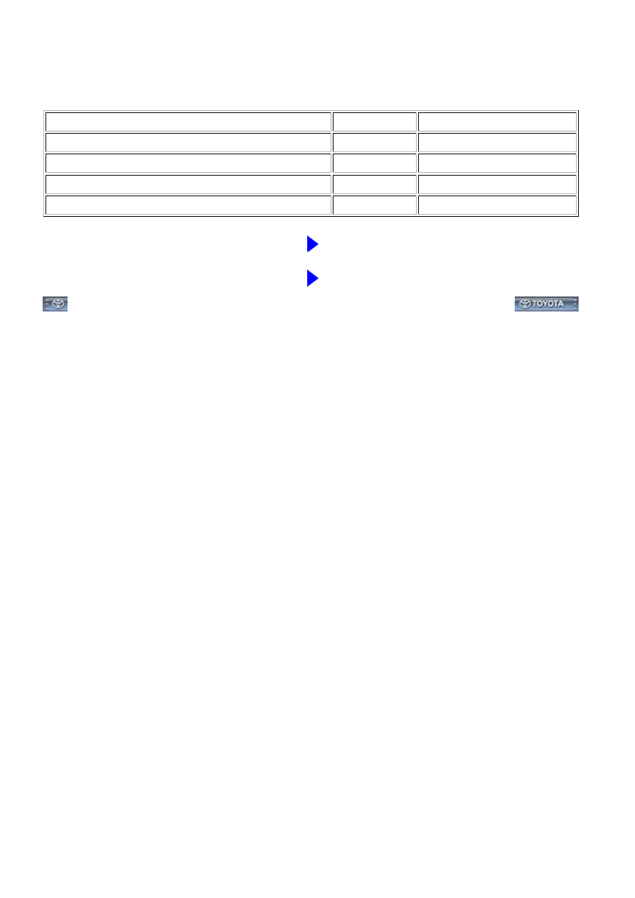
(b) Disconnect the D50 or D54 AID connector.

(c) Measure the resistance according to the value(s) in the table below.

Standard resistance:

TESTER CONNECTION

CONDITION

SPECIFIED CONDITION

D58-5 (+B) - D50-6 (VV)

Always

Below 1 Ω

D59-5 (+BL) - D54-6 (VV2)

Always

Below 1 Ω

D58-5 (+B) or D50-6 (VV) - Body ground

Always

10 kΩ or higher

D59-5 (+BL) or D54-6 (VV2) - Body ground

Always

10 kΩ or higher

NG

REPAIR OR REPLACE HARNESS OR CONNECTOR

OK

REPLACE AIR INJECTION CONTROL DRIVER

3UR-FE ENGINE CONTROL SYSTEM: SFI SYSTEM: P0412,P0415;...

Last Modified: 9-16-2014

6.6 C

Doc ID: RM0000012FZ05TX

Model Year: 2015

Model: Tundra

Prod Date Range: [08/2014 -           ]

Title: 3UR-FE ENGINE CONTROL SYSTEM: SFI SYSTEM: P0418,P0419; Secondary Air Injection System

Control "A" Circuit; 2015 MY Tundra [08/2014 -        ]

DTC

P0418

Secondary Air Injection System Control "A" Circuit

DTC

P0419

Secondary Air Injection System Control "B" Circuit

DESCRIPTION

Refer to DTC P0412 


.

DTC

CODE

DTC DETECTION CONDITION

TROUBLE AREA

P0418

P0419

Secondary Air Injection (AIR) system not

operating (air pump OFF, Air Switching

Valve [ASV] OFF)

a. 

Diagnostic signal from Air Injection Control

Driver (AID) 20%

b. 

Battery voltage 8 V or more

c. 

Open in air pump drive

circuit

Air pump

AID

ECM

P0418

P0419

Secondary Air Injection (AIR) system

operating (air pump ON, Air Switching Valve

[ASV] ON)

a. 

Diagnostic signal from Air Injection Control

Driver (AID) 20%

b. 

Battery voltage 8 V or more

c. 

Short between air pump

drive circuit and body

ground

Air pump

AID

ECM

MONITOR DESCRIPTION

signal to the ECM.

For a short time after cold engine starts, the ECM transmits command signals to the AID to drive the air pump

and ASV.

signals from the ECM to drive the air pump.

The voltage at the AID terminal relating to the air pump is high despite the AID receiving no

command signals from the ECM to drive the air pump.

The ECM sets the DTC based on diagnostic signals from the AID.

3UR-FE ENGINE CONTROL SYSTEM: SFI SYSTEM: P0418,P0419;...

MONITOR STRATEGY

Related DTCs

P0418: Secondary air injection system air pump circuit range check

(Bank 1)

P0419: Secondary air injection system air pump circuit range check

(Bank 2)

Required Sensors/Components (Main)

Air injection control driver

Required Sensors/Components

(Related)

Air pump

Duration

3 seconds

MIL Operation

2 driving cycles

TYPICAL ENABLING CONDITIONS

Case 1:

Monitor runs whenever following DTCs not present

-

(a) Secondary air injection pump

Operating

(b) Secondary air injection switching valve

Operating

Battery voltage

8 V or more

Ignition switch

ON

Starter

OFF

Case 2:

Monitor runs whenever following DTCs not present

-

(a) Secondary air injection pump

Not operating

(b) Secondary air injection switching valve

Not operating

Battery voltage

8 V or more

Ignition switch

ON

Starter

OFF

TYPICAL MALFUNCTION THRESHOLDS

Diagnostic signal duty ratio from air injection control driver

11% or more, and 29% or less

COMPONENT OPERATING RANGE

Diagnostic signal duty ratio from air injection

control driver

70% or more, and 90% or less when secondary air injection

system operating.

0% when secondary air injection system not operating.

3UR-FE ENGINE CONTROL SYSTEM: SFI SYSTEM: P0418,P0419;...

CONFIRMATION DRIVING PATTERN

NOTICE:

the prohibition (WAIT or ERROR).

If an ERROR is displayed on the Techstream during the test, stop the engine for 10 minutes, and

then try again.

1. 

Turn the ignition switch off.

2. 

Connect the Techstream to the DLC3.

3. 

Turn the ignition switch to ON.

4. 

Turn the Techstream on.

5. 

Clear DTCs (if set) 


.

6. 

Turn the ignition switch off and wait for at least 30 seconds.

7. 

Turn the ignition switch to ON and turn the Techstream on [A].

8. 

Enter the following menus: Powertrain / Engine and ECT / Utility / Air injection check / Automatic

Mode.

9. 

Start the engine after the Techstream initialization is finished.

10. 

Perform the System Check operation by pressing ENTER (Next).

11. 

After operating the AIR system, perform the following to confirm the AIR system pending codes:

Press the ENTER (Exit).

12. 

Check pending DTCs [B].

OK:

No pending DTC is output.

13. 

After the "Air injection check" is completed, check for All Readiness by entering the following

menus: Powertrain / Engine and ECT / Utility / All Readiness.

14. 

Input the DTC: P0418 or P0419.

15. 

3UR-FE ENGINE CONTROL SYSTEM: SFI SYSTEM: P0418,P0419;...


Content   ..  1926  1927  1928  1929   ..