Toyota Tundra (2015 year). Manual - part 1863


  Index      Toyota     Toyota Tundra (2015 year) - Service and Repair Manual


Search            copyright infringement  


Content   ..  1861  1862  1863  1864   ..


Toyota Tundra (2015 year). Manual - part 1863


(2) Remove the EFI NO. 1 and ETCS fuses from the engine room relay block located inside the engine

compartment for more than 1 minute.

4. CLEAR PERMANENT DTC

HINT:

Even if the following procedure is not performed, permanent DTCs are cleared by obtaining a normal

judgment during 3 consecutive driving cycles.

(a) Connect the Techstream to the DLC3.

(b) Turn the ignition switch to ON.

(c) Turn the Techstream on.

(d) Enter the following menus: Powertrain / Engine and ECT / Trouble Codes.

(e) Check if permanent DTCs are stored.

HINT:

If permanent DTCs are not output, it is not necessary to continue this procedure.

(f) Clear DTCs.

(g) Perform the respective confirmation driving patterns in order to obtain a normal judgment for the

output DTCs.

HINT:

Confirmation driving patterns do not need to be performed for misfire and fuel system DTCs.

For the confirmation driving pattern, refer to the procedures for the relevant DTC 


.

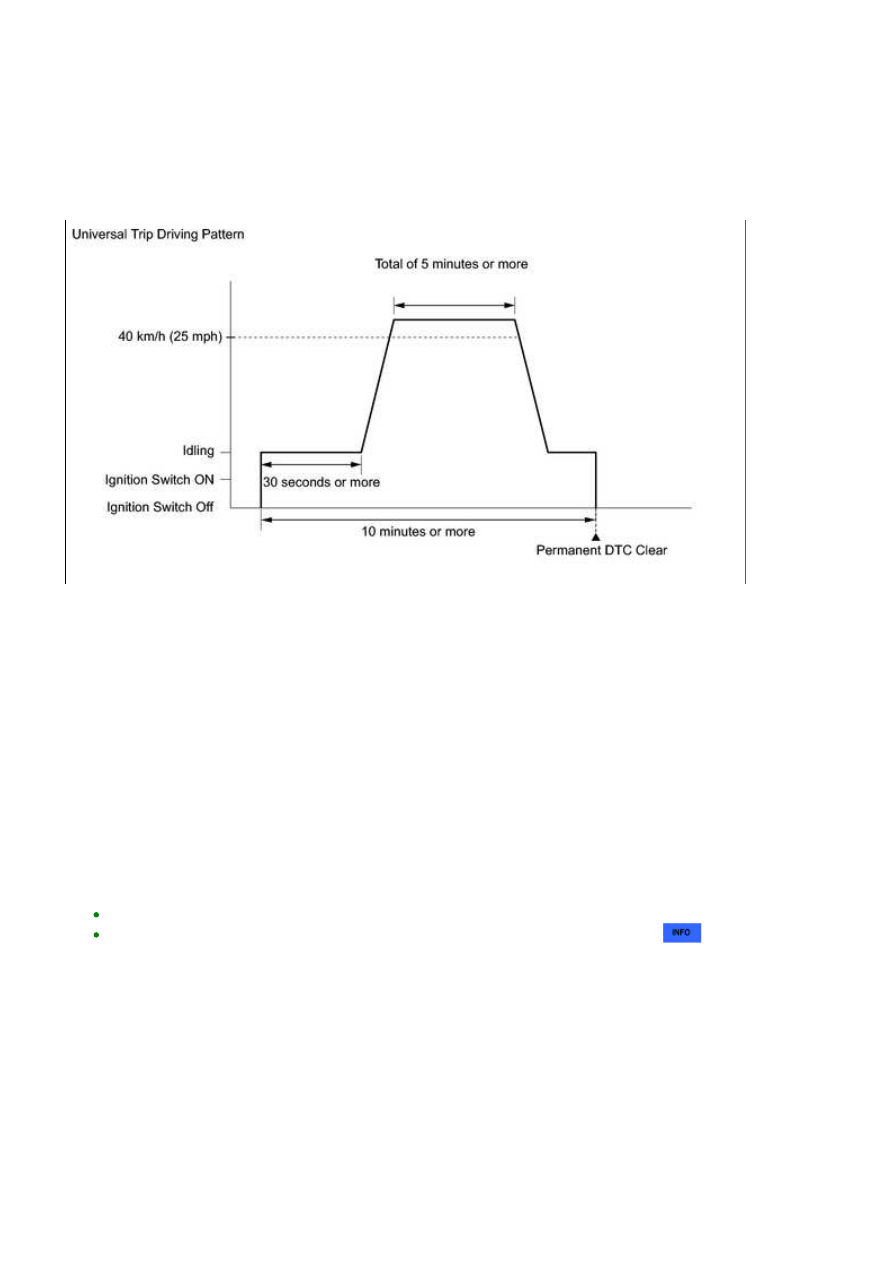
(h) Perform the universal trip.

HINT:

The driving pattern to obtain a normal judgment and the universal trip driving can be performed

consecutively in the same driving cycle.

Idle the engine for 30 seconds or more.

1. 

It is possible to complete the drive pattern even if the vehicle decelerates to less than

3UR-FE ENGINE CONTROL SYSTEM: SFI SYSTEM: DTC CHECK ...

Allow 10 minutes or more to elapse from the time the engine is started.

3. 

(i) Enter the following menus: Powertrain / Engine and ECT / Trouble Codes.

(j) Check that the permanent DTCs have been cleared.

HINT:

The permanent DTCs are cleared when the universal trip is completed.

3UR-FE ENGINE CONTROL SYSTEM: SFI SYSTEM: DTC CHECK ...

Last Modified: 9-16-2014

6.6 D

Doc ID: RM000000PDS137X

Model Year: 2015

Model: Tundra

Prod Date Range: [08/2014 -           ]

Title: 3UR-FE ENGINE CONTROL SYSTEM: SFI SYSTEM: FREEZE FRAME DATA; 2015 MY Tundra [08/2014 -

       ]

FREEZE FRAME DATA

1. DESCRIPTION

Freeze frame data records the engine conditions (fuel system, calculated load, engine coolant

temperature, fuel trim, engine speed, vehicle speed, etc.) when a malfunction is detected. When

troubleshooting, it can help determine if the vehicle was moving or stationary, the engine was warmed

up or not, the air-fuel ratio was Lean or Rich, and other data from the time the malfunction occurred.

HINT:

If it is impossible to duplicate the problem even though a DTC is detected, confirm the freeze

frame data.

3 data sets before the DTC was set.

1 data set when the DTC was set.

1 data set after the DTC was set.

and in judging whether it was temporary or not.

2. LIST OF FREEZE FRAME DATA

TESTER DISPLAY

MEASUREMENT ITEM

DIAGNOSTIC NOTE

Vehicle Speed

Vehicle speed

Speed indicated on speedometer.

Engine Speed

Engine speed

-

Calculate Load

Calculated load

Calculated load by ECM.

Vehicle Load

Vehicle load

-

MAF

Mass air flow volume

If approximately 0.0 gm/sec:

Mass air flow meter power source circuit open or

short.

VG circuit open or short.

3UR-FE ENGINE CONTROL SYSTEM: SFI SYSTEM: FREEZE F...

TESTER DISPLAY

MEASUREMENT ITEM

DIAGNOSTIC NOTE

If 160.0 gm/sec or more:

E2G circuit open.

Atmosphere

Pressure

Atmosphere pressure

-

Coolant Temp

Engine coolant

temperature

If -40°C (-40°F), sensor circuit open.

If 140°C (284°F) or more, sensor circuit shorted.

Intake Air

Intake air

temperature

If -40°C (-40°F), sensor circuit open.

If 140°C (284°F) or more, sensor circuit shorted.

Engine Run Time

Accumulated engine

running time

-

Initial Engine

Coolant Temp

Engine coolant

temperature at engine

start

-

Initial Intake Air

Temp

Intake air

temperature at engine

start

-

Battery Voltage

Battery voltage

-

Accel Sens. No.1

Volt %

Absolute Accelerator

Pedal Position (APP)

No. 1

-

Accel Sens. No.2

Volt %

Absolute APP No. 2

-

Throttle Sensor

Volt %

Throttle sensor

positioning

-

Throttl Sensor #2

Volt %

Throttle sensor

positioning #2

-

Throttle Sensor

Position

Throttle position

-

Throttle Motor

DUTY

Throttle motor

-

Throttle Position

Throttle Position

For use when engine stall, starting problems or rough idle is

present.

ISC Flow

Flow rate calculated

using information from

each sensor

For use when engine stall, starting problems or rough idle is

present.

ISC Position

Requested opening

amount calculated

using ISC control

For use when engine stall, starting problems or rough idle is

present.

ISC Feedback

Value

ISC feedback

compensation amount

For use when engine stall, starting problems or rough idle is

present.

ISC Learning

Value

ISC learned

compensation amount

For use when engine stall, starting problems or rough idle is

present.

Electric Load

Feedback Val

Compensation flow

rate according to

electrical load

For use when engine stall, starting problems or rough idle is

present.

3UR-FE ENGINE CONTROL SYSTEM: SFI SYSTEM: FREEZE F...


Content   ..  1861  1862  1863  1864   ..