Content .. 1859 1860 1861 1862 ..
Toyota Tundra (2015 year). Manual - part 1861
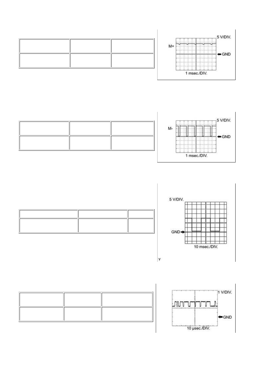
(j) WAVEFORM 9:
Throttle actuator positive terminal
TERMINAL NO.
(SYMBOLS)
TOOL SETTING
CONDITION
D74-19 (M+) - D74-82
(ME01)
5 V/DIV., 1
msec./DIV.
Idling with warm
engine
HINT:
The duty ratio varies depending on the throttle actuator
operation.
(k) WAVEFORM 10:
Throttle actuator negative terminal
TERMINAL NO.
(SYMBOLS)
TOOL SETTING
CONDITION
D74-18 (M-) - D74-82
(ME01)
5 V/DIV., 1
msec./DIV.
Idling with warm
engine
HINT:
The duty ratio varies depending on the throttle actuator
operation.
(l) WAVEFORM 11:
Engine speed signal
TERMINAL NO. (SYMBOLS)
TOOL SETTING
CONDITION
A24-15 (TACH) - D74-81
(E1)
5 V/DIV., 10
msec./DIV.
Idling
HINT:
The wavelength becomes shorter as the engine rpm
increases.
(m) WAVEFORM 12:
CAN communication signal
TERMINAL NO.
(SYMBOLS)
TOOL SETTING
CONDITION
A24-10 (CANH) -
D74-81 (E1)
1 V/DIV., 10
µsec./DIV.
Engine stops and
ignition switch ON
HINT:
The waveform varies depending on the CAN communication
signal.
3UR-FE ENGINE CONTROL SYSTEM: SFI SYSTEM: TERMINALS...