Toyota Tundra (2015 year). Manual - part 1823


  Index      Toyota     Toyota Tundra (2015 year) - Service and Repair Manual


Search            copyright infringement  


Content   ..  1821  1822  1823  1824   ..


Toyota Tundra (2015 year). Manual - part 1823


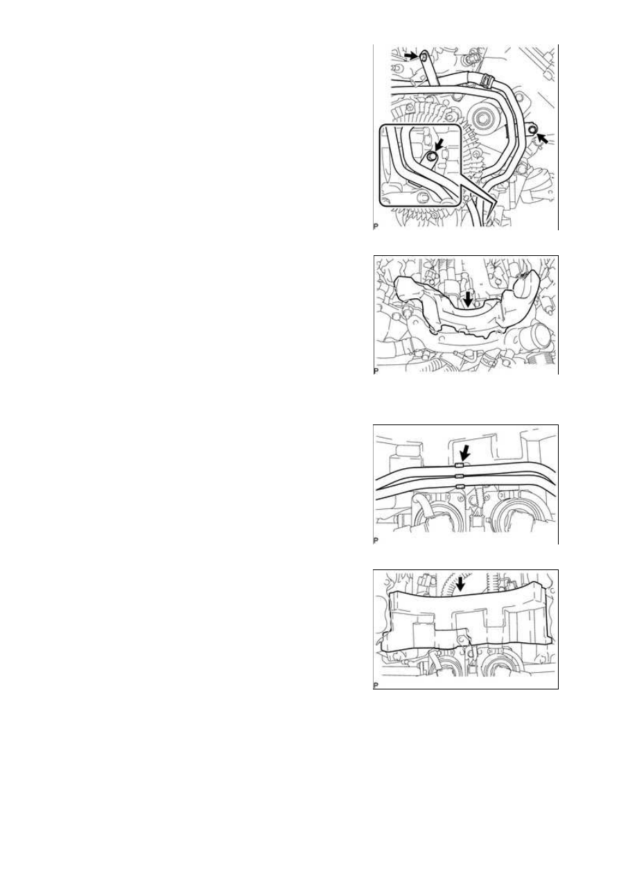
(a) Remove the 3 bolts and disconnect the No. 2 water by-pass

pipe sub-assembly.

8. REMOVE NO. 2 ENGINE COVER

9. DISCONNECT FUEL TUBE CLAMP

(a) Disconnect the fuel tube clamp from the bracket.

10. REMOVE NO. 1 ENGINE COVER

11. REMOVE FRONT WATER BY-PASS JOINT

(a) Disconnect the engine coolant temperature sensor connector.

3UR-FE EMISSION CONTROL: AIR SWITCHING VALVE: REMOVA...

(b) Remove the 4 nuts, front water by-pass joint and 2 gaskets.

12. REMOVE NO. 3 WATER BY-PASS PIPE

HINT:

(a) Remove the bolt and No. 3 water by-pass pipe.

13. REMOVE AIR TUBE

(a) Slide the 2 clamps and disconnect the No. 2 air hose and No.

3 air hose.

Text in Illustration

*1

No. 2 Air Hose

*2

No. 3 Air Hose

(b) Disconnect the air pump connector.

(c) Disconnect the air pump connector clamp holder.

(d) Using a clip remover, detach the wire harness claw.

(e) Remove the 2 bolts and air tube.

(f) Disconnect the 2 No. 1 air hoses from the air tube.

14. REMOVE AIR SWITCHING VALVE ASSEMBLY

3UR-FE EMISSION CONTROL: AIR SWITCHING VALVE: REMOVA...

(a) Disconnect the knock sensor connector.

(b) Remove the bolt and bracket.

(c) Disconnect the 2 air switching valve assembly connectors.

(d) Remove the 3 bolts and air switching valve assembly.

15. REMOVE NO. 2 AIR TUBE

(a) Remove the 2 bolts, No. 2 air tube and gasket.

NOTICE:

16. REMOVE NO. 3 AIR TUBE

(a) Remove the 2 bolts, No. 3 air tube and gasket.

NOTICE:

3UR-FE EMISSION CONTROL: AIR SWITCHING VALVE: REMOVA...

Last Modified: 9-16-2014

6.6 G

Doc ID: RM0000030WF02EX

Model Year: 2015

Model: Tundra

Prod Date Range: [08/2014 -           ]

Title: 3UR-FE EMISSION CONTROL: AIR SWITCHING VALVE: INSPECTION; 2015 MY Tundra [08/2014 -        ]

INSPECTION

1. INSPECT AIR SWITCHING VALVE ASSEMBLY

(a) Measure the resistance according to the value(s) in the table

below.

Standard Resistance:

TESTER CONNECTION

CONDITION

SPECIFIED CONDITION

1 - 5

20°C (68°F)*

4.5 to 5.5 Ω

1 - Body ground

Always

1 MΩ or higher

5 - Body ground

HINT:

*: Make sure that the air switching valve is at ambient

temperature before measuring the resistance.

NOTICE:

When applying voltage, do not touch terminals 2, 3 and 4.

If the result is not as specified, replace the air switching valve

assembly.

NOTICE:

Make sure the applied pressure is 30 kPa (0.3 kgf/cm 

2

 , 4.4 psi) or less

If the result is not as specified, replace the air switching valve assembly.

3UR-FE EMISSION CONTROL: AIR SWITCHING VALVE: INSPEC...


Content   ..  1821  1822  1823  1824   ..