Toyota Tundra (2015 year). Manual - part 180


  Index      Toyota     Toyota Tundra (2015 year) - Service and Repair Manual


Search            copyright infringement  


Content   ..  178  179  180  181   ..


Toyota Tundra (2015 year). Manual - part 180


A

(a) Measure the resistance according to the value(s) in the table

below.

Standard Resistance:

TESTER CONNECTION

CONDITION SPECIFIED CONDITION

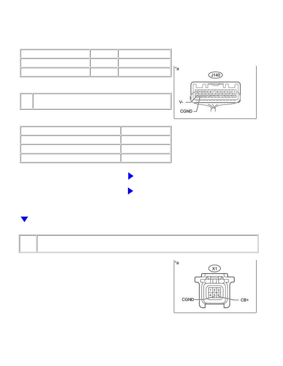
J140-23 (CGND) - Body ground Always

Below 1 Ω

J140-24 (V-) - Body ground

Always

Below 1 Ω

Text in Illustration

*a

Component with harness connected

(Radio and Display Receiver Assembly)

Result

RESULT

PROCEED TO

OK

A

NG (for Column Shift Type)

B

NG (for Floor Shift Type)

C

B

REPLACE RADIO AND DISPLAY RECEIVER ASSEMBLY

C

REPLACE RADIO AND DISPLAY RECEIVER ASSEMBLY

4.

CHECK RADIO AND DISPLAY RECEIVER ASSEMBLY

(a) Disconnect the television camera assembly connector.

(b) Measure the voltage according to the value(s) in the table below.

Standard Voltage:

PARK ASSIST / MONITORING: REAR VIEW MONITOR SYSTEM (f...

A

TESTER CONNECTION

SWITCH CONDITION

SPECIFIED CONDITION

X1-6 (CB+) - X1-5 (CGND)

Ignition switch ACC

5.5 to 7.05 V

Text in Illustration

*a

Result

RESULT

PROCEED TO

OK

A

NG (for Column Shift Type)

B

NG (for Floor Shift Type)

C

B

REPLACE RADIO AND DISPLAY RECEIVER ASSEMBLY

C

REPLACE RADIO AND DISPLAY RECEIVER ASSEMBLY

5.

CHECK TELEVISION CAMERA ASSEMBLY

(a) Using an oscilloscope, check the waveform.

Text in Illustration

*a

Component with harness connected

(Radio and Display Receiver Assembly)

*b

Waveform 1

*c

Waveform 2

*d

Synchronized Signal

PARK ASSIST / MONITORING: REAR VIEW MONITOR SYSTEM (f...

NEXT

*e

Video Waveform

-

-

Measurement Condition

ITEM

CONTENT

Tester Connection

J140-12 (V+) - J140-24 (V-)

Tool Setting

0.2 V/DIV., 50 µs/DIV.

Condition

Waveform 1: Ignition switch ON

Waveform 2: Ignition switch ON, screen blacked out by covering camera lens

OK:

Waveform is as shown in illustration.

HINT:

The video waveform changes according to the image sent by the television camera assembly.

NG

GO TO STEP 6

OK

USE SIMULATION METHOD TO CHECK

6.

REPLACE TELEVISION CAMERA ASSEMBLY

(a) Replace the television camera assembly with a new or normally functioning one 


.

7.

CHECK FOR DTC

(a) Clear the DTCs 


.

(b) Check for DTCs 


.

Result

RESULT

PROCEED TO

No DTC is output

A

DTC is output (for Column Shift Type)

B

DTC is output (for Floor Shift Type)

C

B

REPLACE RADIO AND DISPLAY RECEIVER ASSEMBLY

PARK ASSIST / MONITORING: REAR VIEW MONITOR SYSTEM (f...

C

REPLACE RADIO AND DISPLAY RECEIVER ASSEMBLY

A

END (TELEVISION CAMERA ASSEMBLY WAS

DEFECTIVE)

PARK ASSIST / MONITORING: REAR VIEW MONITOR SYSTEM (f...


Content   ..  178  179  180  181   ..