Toyota Tundra (2015 year). Manual - part 1749


  Index      Toyota     Toyota Tundra (2015 year) - Service and Repair Manual


Search            copyright infringement  


Content   ..  1747  1748  1749  1750   ..


Toyota Tundra (2015 year). Manual - part 1749


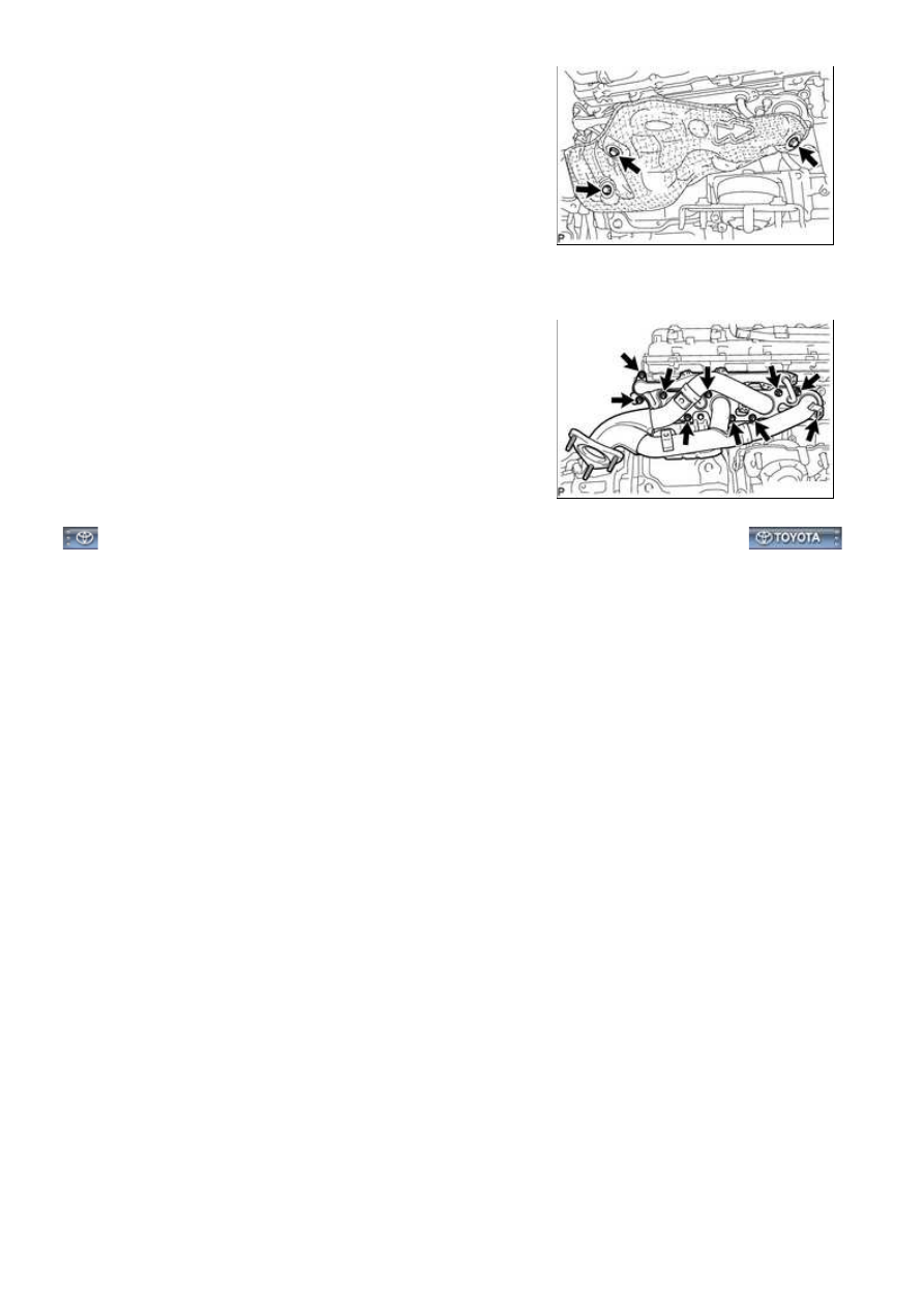
(a) Remove the 3 bolts and heat insulator.

26. REMOVE EXHAUST MANIFOLD SUB-ASSEMBLY RH

(a) Remove the 10 nuts, exhaust manifold and 2 gaskets.

3UR-FBE EXHAUST: EXHAUST MANIFOLD: REMOVAL; 2015 MY...

Last Modified: 9-16-2014

6.6 A

Doc ID: RM0000031GV02EX

Model Year: 2015

Model: Tundra

Prod Date Range: [08/2014 -           ]

Title: 3UR-FBE EXHAUST: EXHAUST MANIFOLD: INSTALLATION; 2015 MY Tundra [08/2014 -        ]

INSTALLATION

1. INSTALL EXHAUST MANIFOLD SUB-ASSEMBLY RH

(a) Install a new gasket to the cylinder head and a new gasket

to the No. 2 air tube.

HINT:

labeled A and 8 new nuts.

(c) Uniformly tighten the nuts that are not labeled A, and then tighten the 2 nuts labeled A.

Torque:

for nut A -

10 N·m {102 kgf·cm, 7ft·lbf}

except nut A -

21 N·m {214 kgf·cm, 15ft·lbf}

2. INSTALL NO. 1 EXHAUST MANIFOLD HEAT INSULATOR

(a) Install the heat insulator with the 3 bolts.

Torque:

10 N·m {102 kgf·cm, 7ft·lbf}

3. INSTALL EXHAUST MANIFOLD SUB-ASSEMBLY LH

3UR-FBE EXHAUST: EXHAUST MANIFOLD: INSTALLATION; 20...

(a) Install a new gasket to the cylinder head and a new gasket

to the No. 3 air tube.

HINT:

labeled A and 8 new nuts.

(c) Uniformly tighten the nuts that are not labeled A, and then tighten the 2 nuts labeled A.

Torque:

for nut A -

10 N·m {102 kgf·cm, 7ft·lbf}

except nut A -

21 N·m {214 kgf·cm, 15ft·lbf}

4. INSTALL NO. 2 EXHAUST MANIFOLD HEAT INSULATOR

(a) Install the heat insulator with the 3 bolts.

Torque:

10 N·m {102 kgf·cm, 7ft·lbf}

5. INSTALL NO. 2 STEERING INTERMEDIATE SHAFT SUB-ASSEMBLY

(a) Align the matchmarks and insert the No. 2 intermediate shaft

into the intermediate shaft.

3UR-FBE EXHAUST: EXHAUST MANIFOLD: INSTALLATION; 20...

(b) Align the matchmarks and insert the No. 2 intermediate

shaft into the power steering gear.

(c) Install the 2 bolts.

Torque:

35 N·m {357 kgf·cm, 26ft·lbf}

6. INSTALL FRONT EXHAUST PIPE ASSEMBLY

7. INSTALL FRONT PROPELLER SHAFT ASSEMBLY

8. CONNECT COOLER COMPRESSOR ASSEMBLY 

9. INSTALL GENERATOR ASSEMBLY 

10. CONNECT VANE PUMP ASSEMBLY 

11. INSTALL ENGINE OIL LEVEL DIPSTICK GUIDE 

12. INSTALL FAN SHROUD 

13. INSTALL FAN AND GENERATOR V-BELT 

14. CONNECT OUTLET RADIATOR HOSE

15. CONNECT INLET RADIATOR HOSE

16. INSTALL AIR CLEANER ASSEMBLY 

17. INSTALL AIR CLEANER HOSE ASSEMBLY 

18. CONNECT CABLE TO NEGATIVE BATTERY TERMINAL

19. ADD ENGINE COOLANT 

20. INSPECT FOR COOLANT LEAK 

21. INSPECT FOR EXHAUST GAS LEAK

If gas is leaking, tighten the areas necessary to stop the leak. Replace damaged parts as necessary.

22. INSTALL FRONT FENDER APRON SEAL REAR LH

(a) Install the fender apron seal with the 5 clips.

23. INSTALL FRONT FENDER APRON SEAL LH

(a) Install the fender apron seal with the 6 clips.

24. INSTALL FRONT FENDER APRON SEAL REAR RH

(a) Install the fender apron seal with the 5 clips.

3UR-FBE EXHAUST: EXHAUST MANIFOLD: INSTALLATION; 20...


Content   ..  1747  1748  1749  1750   ..