Toyota Tundra (2015 year). Manual - part 1725


  Index      Toyota     Toyota Tundra (2015 year) - Service and Repair Manual


Search            copyright infringement  


Content   ..  1723  1724  1725  1726   ..


Toyota Tundra (2015 year). Manual - part 1725


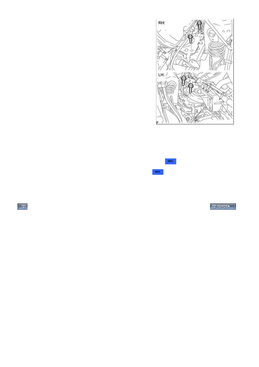
(c) Remove the 4 engine mounting insulator bolts.

(d) Lift the engine out from the vehicle slowly and carefully.

NOTICE:

41. REMOVE EXHAUST MANIFOLD SUB-ASSEMBLY LH 

42. INSTALL ENGINE ON ENGINE STAND

(a) Install the engine onto an engine stand with the bolts.

(b) Remove the 2 bolts and 2 engine hangers.

3UR-FBE ENGINE MECHANICAL: ENGINE ASSEMBLY: REMOVA...

Last Modified: 9-16-2014

6.6 A

Doc ID: RM0000031RQ022X

Model Year: 2015

Model: Tundra

Prod Date Range: [08/2014 -           ]

Title: 3UR-FBE ENGINE MECHANICAL: ENGINE ASSEMBLY: INSTALLATION; 2015 MY Tundra [08/2014 -        ]

INSTALLATION

1. REMOVE ENGINE STAND

(a) Install the 2 engine hangers with the 2 bolts as shown in the

illustration.

Torque:

43 N·m {438 kgf·cm, 32ft·lbf}

ITEM

PART NO.

Engine hanger

12281-38150

Bolt

90119-A0166

(b) Attach an engine sling device and hang the engine with a chain block.

(c) Remove the bolts and engine assembly from the engine stand.

2. INSTALL EXHAUST MANIFOLD SUB-ASSEMBLY LH 

3. INSTALL NO. 2 EXHAUST MANIFOLD HEAT INSULATOR 

4. INSTALL ENGINE ASSEMBLY

(a) Slowly lower the engine assembly into the engine compartment.

NOTICE:

(c) Install the 4 engine mounting insulator bolts.

Torque:

79 N·m {806 kgf·cm, 58ft·lbf}

(d) Remove the 2 bolts and 2 engine hangers.

3UR-FBE ENGINE MECHANICAL: ENGINE ASSEMBLY: INSTALL...

5. INSTALL NO. 1 WATER BY-PASS PIPE

(a) Connect the hose and install the water by-pass pipe with the

2 bolts.

Torque:

18 N·m {184 kgf·cm, 13ft·lbf}

6. INSTALL DRIVE PLATE AND RING GEAR SUB-ASSEMBLY

(a) Using SST, hold the crankshaft.

SST: 09213-70011

SST: 09330-00021

(b) Install the crankshaft angle sensor plate, drive gear and rear drive plate spacer to the crankshaft.

(c) Install and uniformly tighten 10 new bolts in the sequence

shown in the illustration.

Torque:

30 N·m {301 kgf·cm, 22ft·lbf}

NOTICE:

Do not reuse the flywheel installation bolts.
Do not strike or damage the flywheel installation bolts. Be
sure to handle them carefully.

(f) Check that the painted marks are now at a 90° angle to the upside.

7. INSTALL AUTOMATIC TRANSMISSION ASSEMBLY

(a) Install the automatic transmission 


.

8. INSTALL STARTER ASSEMBLY 

9. INSTALL STARTER COVER 

3UR-FBE ENGINE MECHANICAL: ENGINE ASSEMBLY: INSTALL...

10. INSTALL EXHAUST MANIFOLD SUB-ASSEMBLY RH 

11. INSTALL NO. 1 EXHAUST MANIFOLD HEAT INSULATOR 

12. INSTALL ENGINE OIL LEVEL DIPSTICK GUIDE 

13. INSTALL FRONT FENDER APRON SEAL REAR RH 

14. INSTALL FRONT FENDER APRON SEAL RH 

15. INSTALL FRONT PROPELLER SHAFT ASSEMBLY

(a) Install the front propeller shaft 


.

16. INSTALL PROPELLER SHAFT ASSEMBLY

(a) Install the propeller shaft 


.

17. INSTALL EXHAUST PIPE ASSEMBLY

(a) Install the exhaust pipe assembly 


.

18. INSTALL GENERATOR ASSEMBLY 

19. CONNECT VANE PUMP ASSEMBLY 

20. CONNECT COOLER COMPRESSOR ASSEMBLY 

21. CONNECT WIRE HARNESS AND HOSE

(a) Connect the 2 connectors and 2 clips to the engine room

junction block.

(b) Install the engine wire with the nut. Then connect the 2 clips.

Torque:

10 N·m {102 kgf·cm, 7ft·lbf}

(c) Connect the 4 air injection control driver connectors.

(d) Install the ground wire with the bolt.

Torque:

8.0 N·m {82 kgf·cm, 71in·lbf}

(e) Connect the cable to the positive (+) battery terminal.

(f) Install the wire to the positive (+) battery cable with the nut.

Torque:

13 N·m {133 kgf·cm, 10ft·lbf}

3UR-FBE ENGINE MECHANICAL: ENGINE ASSEMBLY: INSTALL...


Content   ..  1723  1724  1725  1726   ..