Toyota Tundra (2015 year). Manual - part 1706


  Index      Toyota     Toyota Tundra (2015 year) - Service and Repair Manual


Search            copyright infringement  


Content   ..  1704  1705  1706  1707   ..


Toyota Tundra (2015 year). Manual - part 1706


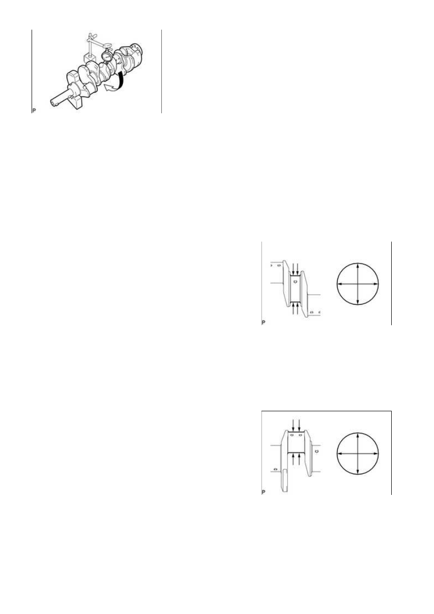
(a) Inspect for circle runout.

(1) Place the crankshaft on V-blocks.

(2) Using a dial indicator, measure the circle runout at the center journal.

Maximum circle runout:

0.06 mm (0.00236 in.)

If the circle runout is more than the maximum, replace the crankshaft.

(b) Inspect the main journals.

Standard journal diameter:

66.988 to 67.000 mm (2.6373 to 2.6378 in.)

If the diameter is not as specified, check the oil

clearance. If necessary, replace the crankshaft.

(2) Check each main journal for taper and out-of-round as

shown in the illustration.

Maximum taper and out-of-round:

0.02 mm (0.000787 in.)

If the taper and out-of-round is more than the maximum,

replace the crankshaft.

(c) Inspect the crank pins.

Standard crank pin diameter:

55.982 to 56.000 mm (2.2040 to 2.2047 in.)

If the diameter is not as specified, check the oil

clearance. If necessary, replace the crankshaft.

(2) Check each crank pin for taper and out-of-round as shown

in the illustration.

Maximum taper and out-of-round:

0.02 mm (0.000787 in.)

If the taper and out-of-round is more than the maximum,

replace the crankshaft.

10. INSPECT CRANKSHAFT OIL CLEARANCE

(a) Clean each main journal and bearing.

(b) Check each main journal and bearing for pitting and scratches.

3UR-FBE ENGINE MECHANICAL: CYLINDER BLOCK: INSPECT...

If the journal or bearing is damaged, replace the bearing.

(c) Place the crankshaft on the cylinder block.


.

(f) Remove the 30 bolts and bearing caps.

(g) Measure the Plastigage at its widest point.

Standard oil clearance:

NUMBER MARK

SPECIFIED CONDITION

No. 1 and No. 5 journals

0.017 to 0.030 mm (0.000669 to 0.00118 in.)

Other journals

0.024 to 0.037 mm (0.000945 to 0.00146 in.)

Maximum oil clearance:

NUMBER MARK

SPECIFIED CONDITION

No. 1 and No. 5 journals

0.050 mm (0.00197 in.)

Other journals

0.060 mm (0.00236 in.)

If the oil clearance is more than the maximum, replace the bearings. If necessary, replace the

crankshaft.

HINT:

3UR-FBE ENGINE MECHANICAL: CYLINDER BLOCK: INSPECT...

Example:

Cylinder block "07" + Crankshaft "06" = Total number 13 (Use upper bearing "6" and lower bearing "7")

HINT:

A = Cylinder block number mark

B = Crankshaft number mark

Standard bearing center wall thickness:

No. 1 and No. 5 journals

(A) +

(B)

UPPER BEARING

LOWER BEARING

NUMBER

MARK

SPECIFIED CONDITION

NUMBER

MARK

SPECIFIED CONDITION

00 to 02 4

2.501 to 2.504 (0.0985 to 0.0986

in.)

5

2.488 to 2.491 (0.0980 to 0.0981

in.)

03 to 05 5

2.504 to 2.507 (0.0986 to 0.0987

in.)

5

2.488 to 2.491 (0.0980 to 0.0981

in.)

06 to 08 5

2.504 to 2.507 (0.0986 to 0.0987

in.)

6

2.491 to 2.494 (0.0981 to 0.0982

in.)

09 to 11 6

2.507 to 2.510 (0.0987 to 0.0988

in.)

6

2.491 to 2.494 (0.0981 to 0.0982

in.)

12 to 14 6

2.507 to 2.510 (0.0987 to 0.0988

in.)

7

2.494 to 2.497 (0.0982 to 0.0983

in.)

15 to 17 7

2.510 to 2.513 (0.0988 to 0.0989

in.)

7

2.494 to 2.497 (0.0982 to 0.0983

in.)

18 to 20 7

2.510 to 2.513 (0.0988 to 0.0989

in.)

8

2.497 to 2.500 (0.0983 to 0.0984

in.)

3UR-FBE ENGINE MECHANICAL: CYLINDER BLOCK: INSPECT...

(A) +

(B)

UPPER BEARING

LOWER BEARING

NUMBER

MARK

SPECIFIED CONDITION

NUMBER

MARK

SPECIFIED CONDITION

21 to 23 8

2.513 to 2.516 (0.0989 to 0.0991

in.)

8

2.497 to 2.500 (0.0983 to 0.0984

in.)

24 to 26 8

2.513 to 2.516 (0.0989 to 0.0991

in.)

9

2.500 to 2.503 (0.0984 to 0.0985

in.)

27 to 28 9

2.516 to 2.519 (0.0991 to 0.0992

in.)

9

2.500 to 2.503 (0.0984 to 0.0985

in.)

Other journals:

(A) +

(B)

UPPER BEARING

LOWER BEARING

NUMBER

MARK

SPECIFIED CONDITION

NUMBER

MARK

SPECIFIED CONDITION

00 to 02 3

2.482 to 2.485 (0.0977 to 0.0978

in.)

4

2.501 to 2.504 (0.0985 to 0.0986

in.)

03 to 05 4

2.485 to 2.488 (0.0978 to 0.0980

in.)

4

2.501 to 2.504 (0.0985 to 0.0986

in.)

06 to 08 4

2.485 to 2.488 (0.0978 to 0.0980

in.)

5

2.504 to 2.507 (0.0986 to 0.0987

in.)

09 to 11 5

2.488 to 2.491 (0.0980 to 0.0981

in.)

5

2.504 to 2.507 (0.0986 to 0.0987

in.)

12 to 14 5

2.488 to 2.491 (0.0980 to 0.0981

in.)

6

2.507 to 2.510 (0.0987 to 0.0988

in.)

15 to 17 6

2.491 to 2.494 (0.0981 to 0.0982

in.)

6

2.507 to 2.510 (0.0987 to 0.0988

in.)

18 to 20 6

2.491 to 2.494 (0.0981 to 0.0982

in.)

7

2.510 to 2.513 (0.0988 to 0.0989

in.)

21 to 23 7

2.494 to 2.497 (0.0982 to 0.0983

in.)

7

2.510 to 2.513 (0.0988 to 0.0989

in.)

24 to 26 7

2.494 to 2.497 (0.0982 to 0.0983

in.)

8

2.513 to 2.516 (0.0989 to 0.0991

in.)

27 to 28 8

2.497 to 2.500 (0.0983 to 0.0984

in.)

8

2.513 to 2.516 (0.0989 to 0.0991

in.)

(h) Completely remove the Plastigage.

11. INSPECT CONNECTING ROD BOLT

(a) Using a vernier caliper, measure the tension portion

8.5 to 8.6 mm (0.335 to 0.339 in.)

Minimum diameter:

8.3 mm (0.327 in.)

If the diameter is less than the minimum, replace the bolt.

3UR-FBE ENGINE MECHANICAL: CYLINDER BLOCK: INSPECT...


Content   ..  1704  1705  1706  1707   ..