Toyota Tundra (2015 year). Manual - part 1705


  Index      Toyota     Toyota Tundra (2015 year) - Service and Repair Manual


Search            copyright infringement  


Content   ..  1703  1704  1705  1706   ..


Toyota Tundra (2015 year). Manual - part 1705


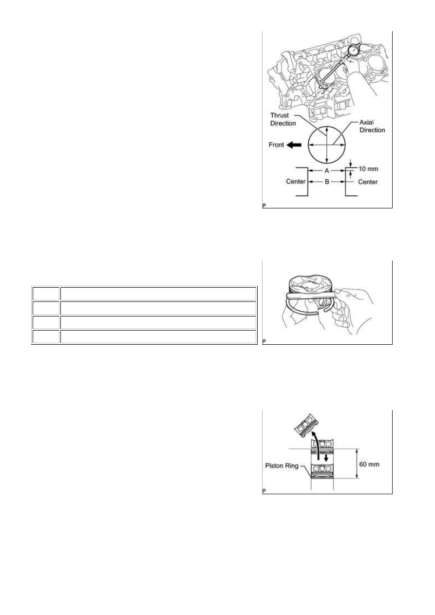
2. INSPECT CYLINDER BORE

(a) Using a cylinder gauge, measure the cylinder bore diameter

at positions A and B in the thrust and axial directions.

Reference value (new parts):

94.000 to 94.012 mm (3.700 to 3.701 in.)

Maximum diameter:

94.200 mm (3.709 in.)

If the diameter is more than the maximum, replace the

cylinder block.

3. INSPECT RING GROOVE CLEARANCE

(a) Using a feeler gauge, measure the clearance between a new

ITEM

SPECIFIED CONDITION

No. 1

0.020 to 0.070 mm (0.000787 to 0.00276 in.)

No. 2

0.020 to 0.060 mm (0.000787 to 0.00236 in.)

Oil

0.070 to 0.145 mm (0.00276 to 0.00571 in.)

If the clearance is not as specified, replace the piston.

4. INSPECT PISTON RING END GAP

(a) Insert the piston ring into the cylinder bore.

(b) Using a piston, push the piston ring a little beyond the

3UR-FBE ENGINE MECHANICAL: CYLINDER BLOCK: INSPECT...

(c) Using a feeler gauge, measure the end gap.

Standard end gap:

ITEM

SPECIFIED CONDITION

No. 1

0.23 to 0.33 mm (0.00906 to 0.0130 in.)

No. 2

0.40 to 0.50 mm (0.0157 to 0.0197 in.)

Oil

0.10 to 0.40 mm (0.00394 to 0.0157 in.)

Maximum end gap:

ITEM

SPECIFIED CONDITION

No. 1

0.42 mm (0.0165 in.)

No. 2

0.55 mm (0.0217 in.)

Oil

0.45 mm (0.0177 in.)

If the end gap is more than the maximum, replace the piston

ring. If the end gap is more than the maximum even with a

new piston ring, replace the cylinder block.

5. INSPECT PISTON SUB-ASSEMBLY WITH PIN

(a) Using a micrometer, measure the piston diameter at a

Reference value (new parts):

93.950 to 93.960 mm (3.6988 to 3.6992 in.)

Minimum diameter:

93.815 mm (3.6935 in.)

If the diameter is less than the minimum, replace the piston.

6. INSPECT PISTON OIL CLEARANCE

(a) Measure the cylinder bore diameter in the thrust direction.

(b) Subtract the piston diameter measurement from the cylinder bore diameter measurement.

Reference value (new parts):

0.040 to 0.062 mm (0.00157 to 0.00244 in.)

Maximum oil clearance:

0.385 mm (0.0152 in.)

If the oil clearance is more than the maximum, replace all the pistons. If necessary, replace the cylinder

block.

7. INSPECT PISTON PIN OIL CLEARANCE

HINT:

(a) Check each mark on the piston, piston pin and connecting

rod.

Standard piston pin hole inside diameter:

MARK

SPECIFIED CONDITION

A

21.998 to 22.001 mm (0.86606 to 0.86618 in.)

B

22.002 to 22.004 mm (0.86622 to 0.86630 in.)

C

22.005 to 22.007 mm (0.86634 to 0.86642 in.)

(c) Using a micrometer, measure the piston pin diameter.

Standard piston pin diameter:

MARK

SPECIFIED CONDITION

A

21.997 to 22.000 mm (0.86602 to 0.86614 in.)

B

22.001 to 22.003 mm (0.86618 to 0.86626 in.)

C

22.004 to 22.006 mm (0.86630 to 0.86638 in.)

(d) Subtract the piston pin diameter measurement from the piston pin hole diameter measurement.

Standard oil clearance:

-0.002 to 0.004 mm (-0.0000787 to 0.000157 in.)

Maximum oil clearance:

3UR-FBE ENGINE MECHANICAL: CYLINDER BLOCK: INSPECT...

0.015 mm (0.000591 in.)

If the oil clearance is more than the maximum, replace the piston and piston pin as a set.

Standard bush inside diameter:

MARK

SPECIFIED CONDITION

A

22.005 to 22.008 mm (0.86634 to 0.86645 in.)

B

22.009 to 22.011 mm (0.86649 to 0.86657 in.)

C

22.012 to 22.014 mm (0.86661 to 0.86669 in.)

(f) Subtract the piston pin diameter measurement from the bush inside diameter measurement.

Standard oil clearance:

0.005 to 0.011 mm (0.000197 to 0.000433 in.)

Maximum oil clearance:

0.03 mm (0.00118 in.)

If the oil clearance is more than the maximum, replace the connecting rod, and replace the piston and

pin as a set.

8. INSPECT CONNECTING ROD SUB-ASSEMBLY

(a) Using a rod aligner and feeler gauge, check the connecting rod alignment.

(1) Check for bend.

Maximum bend:

0.05 mm (0.00197 in.) per 100 mm (3.94 in.)

If the bend is more than the maximum, replace the connecting rod.

(2) Check for twist.

Maximum twist:

0.15 mm (0.00591 in.) per 100 mm (3.94 in.)

If the twist is more than the maximum, replace the

connecting rod.

9. INSPECT CRANKSHAFT

3UR-FBE ENGINE MECHANICAL: CYLINDER BLOCK: INSPECT...


Content   ..  1703  1704  1705  1706   ..