Content .. 1623 1624 1625 1626 ..
Toyota Tundra (2015 year). Manual - part 1625
OK
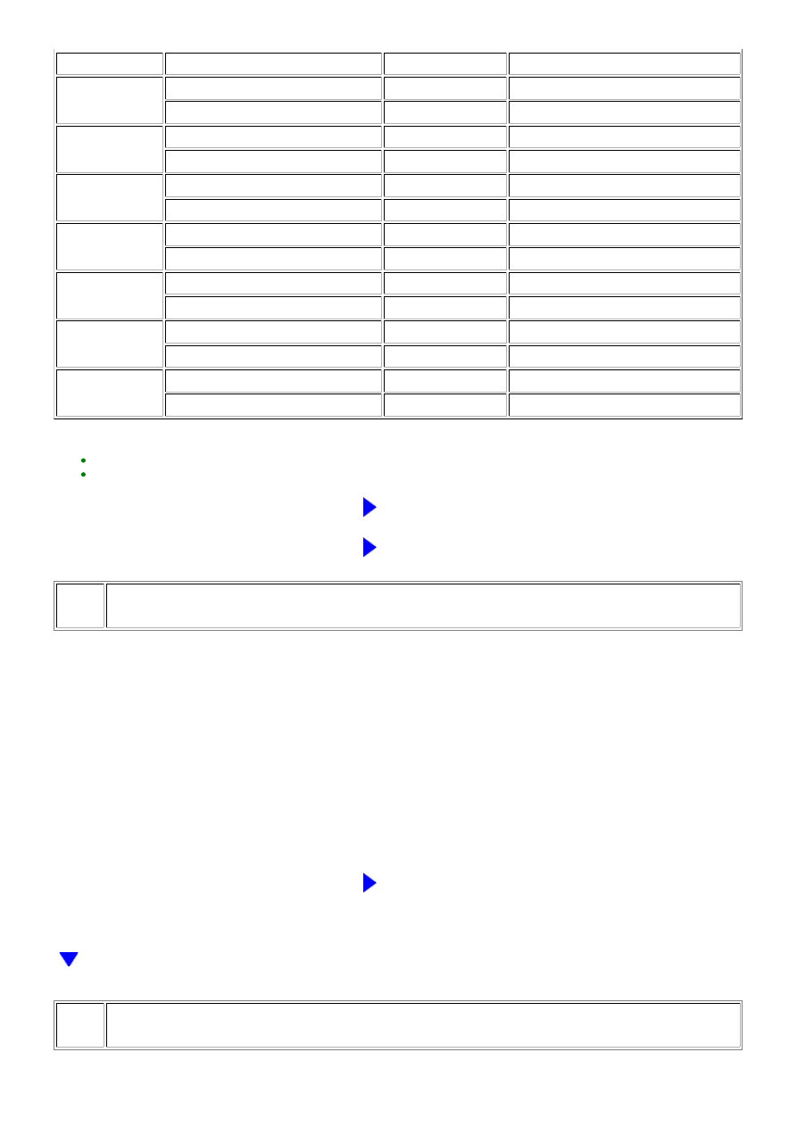
CYLINDER
TESTER CONNECTION
CONDITION
SPECIFIED CONDITION
No. 2
F1-1 - Body ground
Always
10 kΩ or higher
F1-1 - D74-109 (#20)
Always
Below 1 Ω
No. 3
H2-1 - Body ground
Always
10 kΩ or higher
H2-1 - D74-85 (#30)
Always
Below 1 Ω
No. 4
F2-1 - Body ground
Always
10 kΩ or higher
F2-1 - D74-108 (#40)
Always
Below 1 Ω
No. 5
H3-1 - Body ground
Always
10 kΩ or higher
H3-1 - D74-84 (#50)
Always
Below 1 Ω
No. 6
F3-1 - Body ground
Always
10 kΩ or higher
F3-1 - D74-107 (#60)
Always
Below 1 Ω
No. 7
H4-1 - Body ground
Always
10 kΩ or higher
H4-1 - D74-83 (#70)
Always
Below 1 Ω
No. 8
F4-1 - Body ground
Always
10 kΩ or higher
F4-1 - D74-106 (#80)
Always
Below 1 Ω
HINT:
REPAIR OR REPLACE HARNESS OR CONNECTOR
OK
REPLACE ECM
51.
CHECK MASS AIR FLOW METER
(a) Connect the Techstream to the DLC3.
(b) Start the engine and warm it up until the engine coolant temperature reaches 75°C (167°F) or higher.
HINT:
The A/C switch and all accessory switches should be off, and the shift lever should be in N or P.
(c) Turn the Techstream on.
(d) Enter the following menus: Powertrain / Engine and ECT / Data List / MAF.
(e) Check MAF in the Data List during idling.
Standard:
4.0 to 8.0 gm/sec.
NG
GO TO STEP 57
52.
CHECK INTAKE SYSTEM
3UR-FBE ENGINE CONTROL SYSTEM: SFI SYSTEM: P1604; Start...