Content .. 1622 1623 1624 1625 ..
Toyota Tundra (2015 year). Manual - part 1624
OK
OK
CHECK POWER SOURCE CIRCUIT
44.
CHECK HARNESS AND CONNECTOR (IGNITION COIL - ECM)
(a) Disconnect the ignition coil connector.
(b) Disconnect the ECM connector.
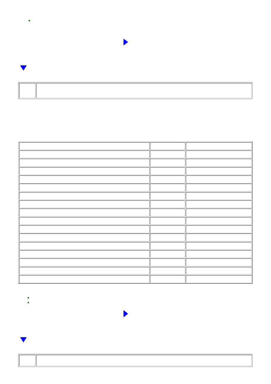
(c) Measure the resistance according to the value(s) in the table below.
Standard Resistance:
TESTER CONNECTION
CONDITION
SPECIFIED CONDITION
D10-2 (IGF1) - D74-104 (IGF1)
Always
Below 1 Ω
D25-2 (IGF2) - D74-105 (IGF2)
Always
Below 1 Ω
D12-2 (IGF2) - D74-105 (IGF2)
Always
Below 1 Ω
D23-2 (IGF1) - D74-104 (IGF1)
Always
Below 1 Ω
D14-2 (IGF2) - D74-105 (IGF2)
Always
Below 1 Ω
D21-2 (IGF1) - D74-104 (IGF1)
Always
Below 1 Ω
D16-2 (IGF1) - D74-104 (IGF1)
Always
Below 1 Ω
D19-2 (IGF2) - D74-105 (IGF2)
Always
Below 1 Ω
D10-2 (IGF1) or D74-104 (IGF1) - Body ground
Always
10 kΩ or higher
D25-2 (IGF2) or D74-105 (IGF2) - Body ground
Always
10 kΩ or higher
D12-2 (IGF2) or D74-105 (IGF2) - Body ground
Always
10 kΩ or higher
D23-2 (IGF1) or D74-104 (IGF1) - Body ground
Always
10 kΩ or higher
D14-2 (IGF2) or D74-105 (IGF2) - Body ground
Always
10 kΩ or higher
D21-2 (IGF1) or D74-104 (IGF1) - Body ground
Always
10 kΩ or higher
D16-2 (IGF1) or D74-104 (IGF1) - Body ground
Always
10 kΩ or higher
D19-2 (IGF2) or D74-105 (IGF2) - Body ground
Always
10 kΩ or higher
HINT:
REPAIR OR REPLACE HARNESS OR CONNECTOR
45.
CHECK HARNESS AND CONNECTOR (IGNITION COIL - ECM)
3UR-FBE ENGINE CONTROL SYSTEM: SFI SYSTEM: P1604; Start...