Toyota Tundra (2015 year). Manual - part 162
2.
CHECK HARNESS AND CONNECTOR (FRONT CORNER SENSOR LH - FRONT CORNER
SENSOR RH)
(a) Disconnect the C1 No. 1 ultrasonic sensor (front corner sensor LH) connector.
(b) Disconnect the B1 No. 1 ultrasonic sensor (front corner sensor RH) connector.
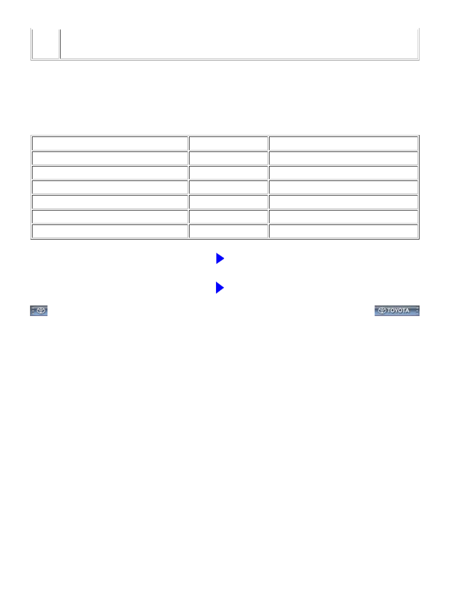
(c) Measure the resistance according to the value(s) in the table below.
Standard Resistance:
TESTER CONNECTION
CONDITION
SPECIFIED CONDITION
C1-1 (BI) - B1-2 (BO)
Always
Below 1 Ω
C1-3 (SI) - B1-4 (SO)
Always
Below 1 Ω
C1-5 (EI) - B1-6 (EO)
Always
Below 1 Ω
C1-1 (BI) - Body ground
Always
10 kΩ or higher
C1-3 (SI) - Body ground
Always
10 kΩ or higher
C1-5 (EI) - Body ground
Always
10 kΩ or higher
NG
REPAIR OR REPLACE HARNESS OR CONNECTOR
OK
PROCEED TO NEXT SUSPECTED AREA SHOWN IN
PROBLEM SYMPTOMS TABLE
PARK ASSIST / MONITORING: INTUITIVE PARKING ASSIST SY...