Toyota Tundra (2015 year). Manual - part 1611


  Index      Toyota     Toyota Tundra (2015 year) - Service and Repair Manual


Search            copyright infringement  


Content   ..  1609  1610  1611  1612   ..


Toyota Tundra (2015 year). Manual - part 1611


A

A

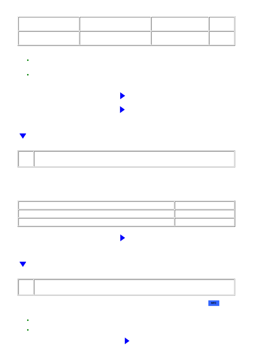
FREEZE FRAME DATA ITEM

FOR DTC P1605

RESULT

SUSPECTED AREA

PROCEED

TO

Both freeze frame data items

listed above

Values are other than above

-

C

HINT:

GO TO STEP 43

C

GO TO STEP 46

40.

CHECK MASS AIR FLOW METER

(a) Remove the mass airflow meter.

RESULT

PROCEED TO

Visible foreign matter is not present

A

Visible foreign matter is present

B

B

REPLACE MASS AIR FLOW METER

41.

CHECK HARNESS AND CONNECTOR (ECM - MASS AIR FLOW METER)

(a) Check the harnesses and connectors, referring to DTC P0102 inspection procedure 


.

HINT:

REPAIR OR REPLACE HARNESS OR CONNECTOR

3UR-FBE ENGINE CONTROL SYSTEM: SFI SYSTEM: P1603,P160...

OK

OK

42.

PERFORM DRIVE TEST

(a) Connect the Techstream to the DLC3.

(b) Start the engine and warm it up until the engine coolant temperature stabilizes.

HINT:

The A/C switch and all accessory switches should be off.

(c) Idle the engine.

DATA LIST

SPECIFIED CONDITION

Calculate Load

REPLACE MASS AIR FLOW METER

43.

PERFORM ACTIVE TEST USING TECHSTREAM (CONTROL THE INJECTION VOLUME
FOR A/F SENSOR)

3UR-FBE ENGINE CONTROL SYSTEM: SFI SYSTEM: P1603,P160...

(a) Connect the Techstream to the DLC3.

(b) Turn the ignition switch to ON.

(c) Start the engine, turn off all accessory switches and warm up the engine until the engine

coolant temperature stabilizes.

(d) Idle the engine.

(e) Enter the following menus: Powertrain / Engine and ECT / Active Test / Control the Injection

Volume for A/F Sensor.

(f) Read the output voltage from the air fuel ratio sensor when increasing and decreasing the fuel

injection volume.

Standard:

TECHSTREAM DISPLAY

SPECIFIED CONDITION

Control the Injection Volume for A/F Sensor

(+12.5%)

Air fuel ratio sensor output voltage is below 3.1 V

Control the Injection Volume for A/F Sensor (-12.5%)

Air fuel ratio sensor output voltage is higher than 3.4

V

Result

RESULT

PROCEED TO

Abnormal

A

Normal

B

HINT:

3UR-FBE ENGINE CONTROL SYSTEM: SFI SYSTEM: P1603,P160...

A

OK

OK

B

GO TO STEP 46

44.

CHECK TERMINAL VOLTAGE (AIR FUEL RATIO SENSOR POWER SOURCE)

(a) Check the harnesses and connectors, referring to DTC P0031 inspection procedure 


.

HINT:

REPAIR AIR FUEL RATIO SENSOR POWER

SOURCE CIRCUIT

45.

CHECK HARNESS AND CONNECTOR (AIR FUEL RATIO SENSOR - ECM)

(a) Check the harnesses and connectors, referring to DTC P0031 inspection procedure 


.

HINT:

REPAIR OR REPLACE HARNESS OR CONNECTOR

46.

READ FREEZE FRAME DATA

(a) Connect the Techstream to the DLC3.

(b) Turn the ignition switch to ON.

(c) Using the Techstream, confirm the vehicle conditions recorded in the freeze frame data which

were present when the DTC was stored 


.

Result

3UR-FBE ENGINE CONTROL SYSTEM: SFI SYSTEM: P1603,P160...


Content   ..  1609  1610  1611  1612   ..