Toyota Tundra (2015 year). Manual - part 1598


  Index      Toyota     Toyota Tundra (2015 year) - Service and Repair Manual


Search            copyright infringement  


Content   ..  1596  1597  1598  1599   ..


Toyota Tundra (2015 year). Manual - part 1598


OK

PROCEDURE

1.

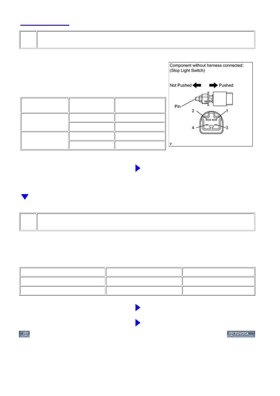
INSPECT STOP LIGHT SWITCH

(a) Remove the stop light switch.

(b) Measure the resistance according to the value(s) in the

table below.

Standard resistance:

TESTER

CONNECTION

SWITCH

CONDITION

SPECIFIED

CONDITION

1 - 2

Pin not pushed

Below 1 Ω

Pin pushed

10 kΩ or higher

3 - 4

Pin not pushed

10 kΩ or higher

Pin pushed

Below 1 Ω

NG

REPLACE STOP LIGHT SWITCH

2.

CHECK HARNESS AND CONNECTOR (ECM - BATTERY)

(a) Disconnect the A24 ECM connector.

(b) Measure the voltage according to the value(s) in the table below.

Standard voltage:

TESTER CONNECTION

CONDITION

SPECIFIED CONDITION

A24-36 (STP) - Body ground

Brake pedal is depressed

11 to 14 V

A24-36 (STP) - Body ground

Brake pedal is released

Below 1 V

NG

REPAIR OR REPLACE HARNESS OR CONNECTOR

OK

REPLACE ECM

3UR-FBE ENGINE CONTROL SYSTEM: SFI SYSTEM: P0724; Brak...

Last Modified: 9-16-2014

6.6 C

Doc ID: RM00000434H00AX

Model Year: 2015

Model: Tundra

Prod Date Range: [08/2014 -           ]

Title: 3UR-FBE ENGINE CONTROL SYSTEM: SFI SYSTEM: P106B; Evaporative Emission System Pressure

Sensor - Secondary Air Injection Pressure Sensor Correlation; 2015 MY Tundra [08/2014 -        ]

DTC

P106B

Evaporative Emission System Pressure Sensor - Secondary Air Injection

Pressure Sensor Correlation

DESCRIPTION

DTC

NO.

DTC DETECTION CONDITION

TROUBLE AREA

P106B

The pressure detected by the canister pressure sensor (Vapor

Pressure Pump*) and the pressure detected by the pressure sensor of

either air switching valve assembly (for Bank 1 or Bank 2) (Air pump

pressure (Absolute)*1 or Air Pump2 Pressure (Absolute)*1) differ by

6.98 kPa (52 mmHg) or more (2 trip detection logic).

Canister pump

module (Canister

pressure sensor)*2

Charcoal canister

assembly*3

Air switching valve

assembly

HINT:

This DTC is stored when a deviation from pressure sensor characteristics is detected.

The pressure detected by the canister pressure sensor and the pressures detected by the pressure sensors of

both air switching valves (for Bank 1 or Bank 2) are checked 55 minutes after the ignition switch is turned off.

If the pressure detected by the canister pressure sensor and the pressure detected by the pressure sensor of

either air switching valve differ by a certain amount, the MIL is illuminated and a DTC is stored (2 trip

detection logic).

HINT:

Correct judgment may not be possible when the altitude is 4000 m (13120 ft.) or more.

MONITOR STRATEGY

Related DTC

P106B: Evaporative emission system pressure sensor - Secondary Air

injection (AIR) system pressure sensor correlation

Required Sensors/Components

(Main)

Canister pressure sensor

Pressure sensor

Required Sensors/Components

(Related)

-

Duration

Less than 65 seconds

MIL Operation

2 driving cycles

3UR-FBE ENGINE CONTROL SYSTEM: SFI SYSTEM: P106B; Eva...

TYPICAL ENABLING CONDITIONS

Monitor runs whenever following DTCs

are not stored

P0452, P0453 (Evaporative Emission System Pressure Sensor)

P2431, P2432, P2433, P2436, P2437, P2438 (Secondary air

injection system pressure sensor)

P2440, P2441, P2442, P2443, P2444, P2445, P2446, P2447

(Secondary air injection system)

Time elapsed after engine stop

50 minutes

Time after ECM started by soak-timer

60 seconds or more

Battery voltage

10.5 V or higher

Intake air temperature

-10°C (14°F) or higher

Engine coolant temperature

-10°C (14°F) or higher

TYPICAL MALFUNCTION THRESHOLDS

Difference between EVAP pressure and secondary air pressure sensor (bank

1)

More than 6.98 kPa (52

mmHg)

Difference between EVAP pressure and secondary air pressure sensor (bank

2)

More than 6.98 kPa (52

mmHg)

CONFIRMATION DRIVING PATTERN

Connect the Techstream to the DLC3.

1. 

Turn the ignition switch to ON and turn the Techstream on [A].

2. 

Clear the DTCs (even if no DTCs are stored, perform the clear DTC operation).

3. 

Start the engine and idle it for 10 seconds [B].

4. 

Turn the ignition switch off.

5. 

Soak the vehicle for 55 minutes [C].

6. 

Turn the ignition switch to ON and turn the Techstream on.

7. 

Enter the following menus: Powertrain / Engine and ECT / Trouble Codes [D].

8. 

Read the Pending DTCs.

9. 

3UR-FBE ENGINE CONTROL SYSTEM: SFI SYSTEM: P106B; Eva...

HINT:

If a pending DTC is output, the system is malfunctioning.
If a pending DTC is not output, perform the following procedure.

Enter the following menus: Powertrain / Engine and ECT / Utility / All Readiness.

10. 

Input the DTC: P106B.

11. 

Check the DTC judgment result.

TECHSTREAM

DISPLAY

DESCRIPTION

NORMAL

DTC judgment completed

System normal

ABNORMAL

DTC judgment completed

System abnormal

INCOMPLETE

DTC judgment not completed

Perform driving pattern after confirming DTC enabling conditions

N/A

Unable to perform DTC judgment

HINT:

If the judgment result shows ABNORMAL, the system has a malfunction.
If the judgment result shows INCOMPLETE or N/A, perform steps [A] through [D] again.

12. 

If no pending DTC is output, perform a universal trip and check for permanent DTCs 


.

HINT:

If a permanent DTC is output, the system is malfunctioning
If no permanent DTC is output, the system is normal.

13. 

INSPECTION PROCEDURE

HINT:

Read freeze frame data using the Techstream. The ECM records vehicle and driving condition

1.

CHECK ANY OTHER DTCS OUTPUT (IN ADDITION TO P106B)

(a) Connect the Techstream to the DLC3.

(b) Turn the ignition switch to ON.

(c) Turn the Techstream on.

(d) Enter the following menus: Powertrain / Engine and ECT / Trouble Codes.

(e) Read the DTCs.

3UR-FBE ENGINE CONTROL SYSTEM: SFI SYSTEM: P106B; Eva...


Content   ..  1596  1597  1598  1599   ..