Content .. 1574 1575 1576 1577 ..
Toyota Tundra (2015 year). Manual - part 1576
A
(a) Move the shift lever to the neutral position.
(b) Jack up the vehicle.
(c) Turn the ignition switch to ON.
(d) Measure the voltage according to the value(s) in the table below.
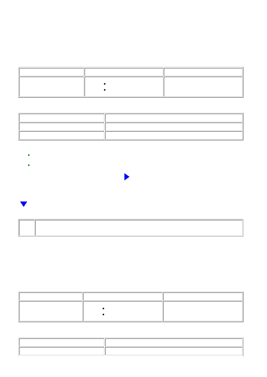
Standard voltage:
TESTER CONNECTION
CONDITION
SPECIFIED CONDITION
J28-29 (+S) - Body ground
Ignition switch ON
Wheel is turned slowly
Voltage generated intermittently
Result
RESULT
PROCEED TO
NG
A
OK
B
HINT:
REPLACE ECM
6.
CHECK COMBINATION METER ASSEMBLY (SPD SIGNAL INPUT WAVEFORM)
(a) Move the shift lever to the neutral position.
(b) Jack up the vehicle.
(c) Turn the ignition switch to ON.
(d) Measure the voltage according to the value(s) in the table below.
Standard voltage:
TESTER CONNECTION
CONDITION
SPECIFIED CONDITION
J28-30 (SI) - Body ground
Ignition switch ON
Wheel is turned slowly
Voltage generated intermittently
Result
RESULT
PROCEED TO
NG
A
3UR-FBE ENGINE CONTROL SYSTEM: SFI SYSTEM: P0500; Vehic...