Toyota Tundra (2015 year). Manual - part 1552


  Index      Toyota     Toyota Tundra (2015 year) - Service and Repair Manual


Search            copyright infringement  


Content   ..  1550  1551  1552  1553   ..


Toyota Tundra (2015 year). Manual - part 1552


INSPECTION PROCEDURE

HINT:

Read freeze frame data using the Techstream. Freeze frame data records the engine condition when

malfunctions are detected. When troubleshooting, freeze frame data can help determine if the vehicle
was moving or stationary, if the engine was warmed up or not, if the air-fuel ratio was lean or rich, and
other data from the time the malfunction occurred.

PROCEDURE

1.

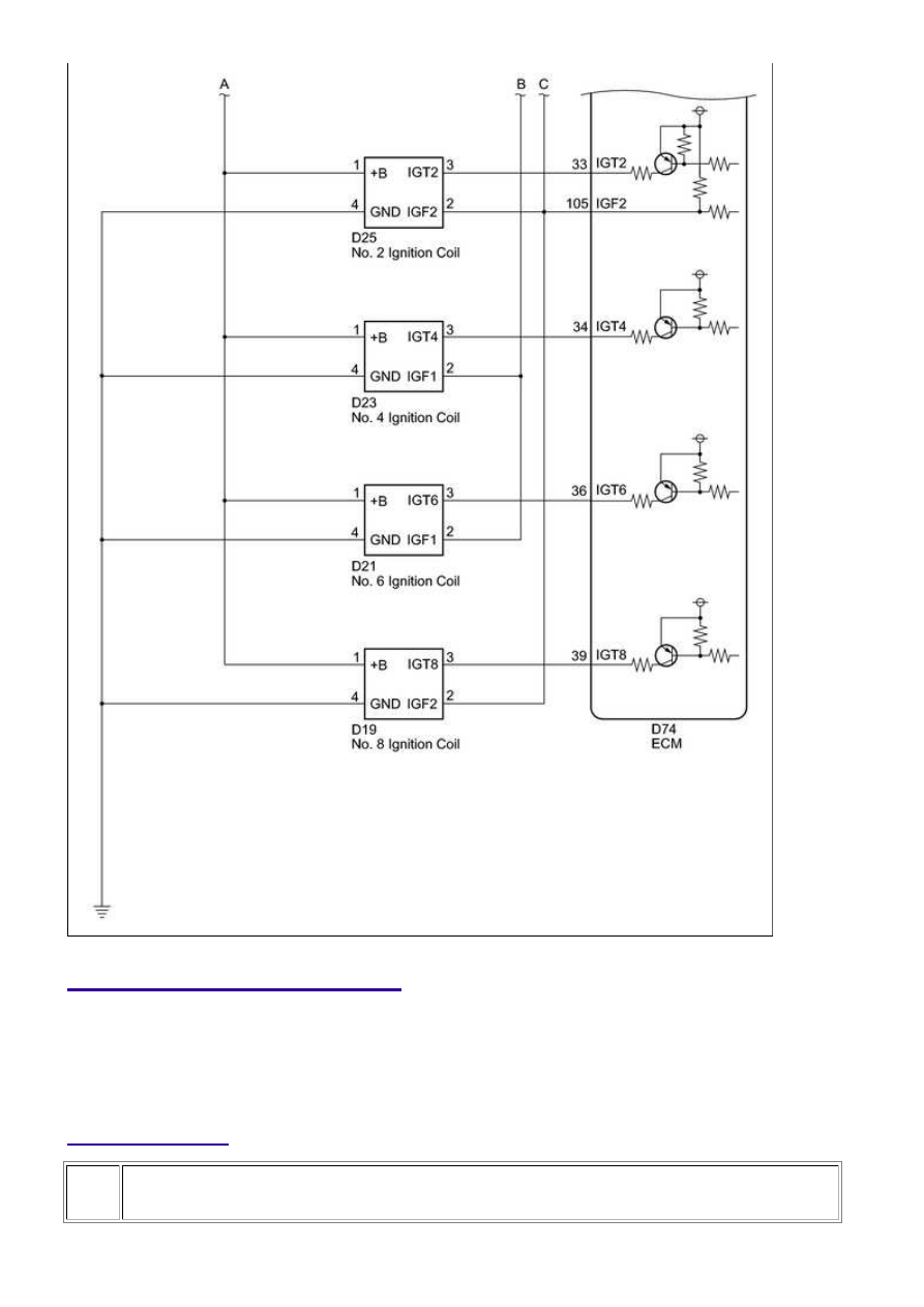
INSPECT IGNITION COIL (POWER SOURCE)

3UR-FBE ENGINE CONTROL SYSTEM: SFI SYSTEM: P0351-P0358...

OK

(a) Disconnect the D10, D12, D14, D16, D19, D21, D23 or

D25 ignition coil connector.

(b) Measure the resistance according to the value(s) in the

table below.

Standard resistance:

TESTER CONNECTION

CONDITION SPECIFIED CONDITION

D10-4 (GND) - Body ground

Always

Below 1 Ω

D25-4 (GND) - Body ground

Always

Below 1 Ω

D12-4 (GND) - Body ground

Always

Below 1 Ω

D23-4 (GND) - Body ground

Always

Below 1 Ω

D14-4 (GND) - Body ground

Always

Below 1 Ω

D21-4 (GND) - Body ground

Always

Below 1 Ω

D16-4 (GND) - Body ground

Always

Below 1 Ω

D19-4 (GND) - Body ground

Always

Below 1 Ω

(c) Turn the ignition switch to ON.

(d) Measure the voltage according to the value(s) in the

table below.

Standard voltage:

TESTER CONNECTION

SWITCH

CONDITION

SPECIFIED

CONDITION

D10-1 (+B) - D10-4

(GND)

Ignition switch ON

11 to 14 V

D25-1 (+B) - D25-4

(GND)

Ignition switch ON

11 to 14 V

D12-1 (+B) - D12-4

(GND)

Ignition switch ON

11 to 14 V

D23-1 (+B) - D23-4

(GND)

Ignition switch ON

11 to 14 V

D14-1 (+B) - D14-4

(GND)

Ignition switch ON

11 to 14 V

D21-1 (+B) - D21-4

(GND)

Ignition switch ON

11 to 14 V

D16-1 (+B) - D16-4

(GND)

Ignition switch ON

11 to 14 V

D19-1 (+B) - D19-4

(GND)

Ignition switch ON

11 to 14 V

NG

REPAIR OR REPLACE HARNESS OR CONNECTOR

3UR-FBE ENGINE CONTROL SYSTEM: SFI SYSTEM: P0351-P0358...

2.

CHECK HARNESS AND CONNECTOR (IGNITION COIL - ECM)

(a) Disconnect the D10, D12, D14, D16, D19, D21, D23 or D25 ignition coil connector.

(b) Disconnect the D74 ECM connector.

(c) Measure the resistance according to the value(s) in the table below.

Standard resistance:

TESTER CONNECTION

CONDITION

SPECIFIED CONDITION

D10-2 (IGF1) - D74-104 (IGF1)

Always

Below 1 Ω

D25-2 (IGF2) - D74-105 (IGF2)

Always

Below 1 Ω

D12-2 (IGF2) - D74-105 (IGF2)

Always

Below 1 Ω

D23-2 (IGF1) - D74-104 (IGF1)

Always

Below 1 Ω

D14-2 (IGF2) - D74-105 (IGF2)

Always

Below 1 Ω

D21-2 (IGF1) - D74-104 (IGF1)

Always

Below 1 Ω

D16-2 (IGF1) - D74-104 (IGF1)

Always

Below 1 Ω

D19-2 (IGF2) - D74-105 (IGF2)

Always

Below 1 Ω

D10-3 (IGT1) - D74-40 (IGT1)

Always

Below 1 Ω

D25-3 (IGT2) - D74-33 (IGT2)

Always

Below 1 Ω

D12-3 (IGT3) - D74-37 (IGT3)

Always

Below 1 Ω

D23-3 (IGT4) - D74-34 (IGT4)

Always

Below 1 Ω

D14-3 (IGT5) - D74-35 (IGT5)

Always

Below 1 Ω

D21-3 (IGT6) - D74-36 (IGT6)

Always

Below 1 Ω

D16-3 (IGT7) - D74-38 (IGT7)

Always

Below 1 Ω

D19-3 (IGT8) - D74-39 (IGT8)

Always

Below 1 Ω

D10-2 (IGF1) or D74-104 (IGF1) - Body ground

Always

10 kΩ or higher

D25-2 (IGF2) or D74-105 (IGF2) - Body ground

Always

10 kΩ or higher

D12-2 (IGF2) or D74-105 (IGF2) - Body ground

Always

10 kΩ or higher

D23-2 (IGF1) or D74-104 (IGF1) - Body ground

Always

10 kΩ or higher

D14-2 (IGF2) or D74-105 (IGF2) - Body ground

Always

10 kΩ or higher

D21-2 (IGF1) or D74-104 (IGF1) - Body ground

Always

10 kΩ or higher

D16-2 (IGF1) or D74-104 (IGF1) - Body ground

Always

10 kΩ or higher

D19-2 (IGF2) or D74-105 (IGF2) - Body ground

Always

10 kΩ or higher

D10-3 (IGT1) or D74-40 (IGT1) - Body ground

Always

10 kΩ or higher

D25-3 (IGT2) or D74-33 (IGT2) - Body ground

Always

10 kΩ or higher

D12-3 (IGT3) or D74-37 (IGT3) - Body ground

Always

10 kΩ or higher

D23-3 (IGT4) or D74-34 (IGT4) - Body ground

Always

10 kΩ or higher

3UR-FBE ENGINE CONTROL SYSTEM: SFI SYSTEM: P0351-P0358...

OK

TESTER CONNECTION

CONDITION

SPECIFIED CONDITION

D14-3 (IGT5) or D74-35 (IGT5) - Body ground

Always

10 kΩ or higher

D21-3 (IGT6) or D74-36 (IGT6) - Body ground

Always

10 kΩ or higher

D16-3 (IGT7) or D74-38 (IGT7) - Body ground

Always

10 kΩ or higher

D19-3 (IGT8) or D74-39 (IGT8) - Body ground

Always

10 kΩ or higher

NG

REPAIR OR REPLACE HARNESS OR CONNECTOR

3.

CHECK WHETHER DTC OUTPUT RECURS (DTC P0351, P0352, P0353, P0354,
P0355, P0356, P0357 OR P0358)

(a) Connect the Techstream to the DLC3.

(b) Turn the ignition switch to ON and turn the Techstream on.

(c) Clear DTCs 


.

Do not shuffle the connectors.

(e) Perform a simulation test.

(f) Check DTCs displayed on the Techstream.

Result

RESULT

PROCEED TO

Same DTC is output

A

Different ignition coil DTC is output

B

B

REPLACE IGNITION COIL

A

REPLACE ECM

3UR-FBE ENGINE CONTROL SYSTEM: SFI SYSTEM: P0351-P0358...


Content   ..  1550  1551  1552  1553   ..