Content .. 1527 1528 1529 1530 ..
Toyota Tundra (2015 year). Manual - part 1529
DISPLAY ITEM (SENSOR)
INJECTION VOLUME
STATUS
VOLTAGE
O2S B1S2 or O2S B2S2
(HO2)
-12.5%
Lean
Less than 0.4 V
NOTICE:
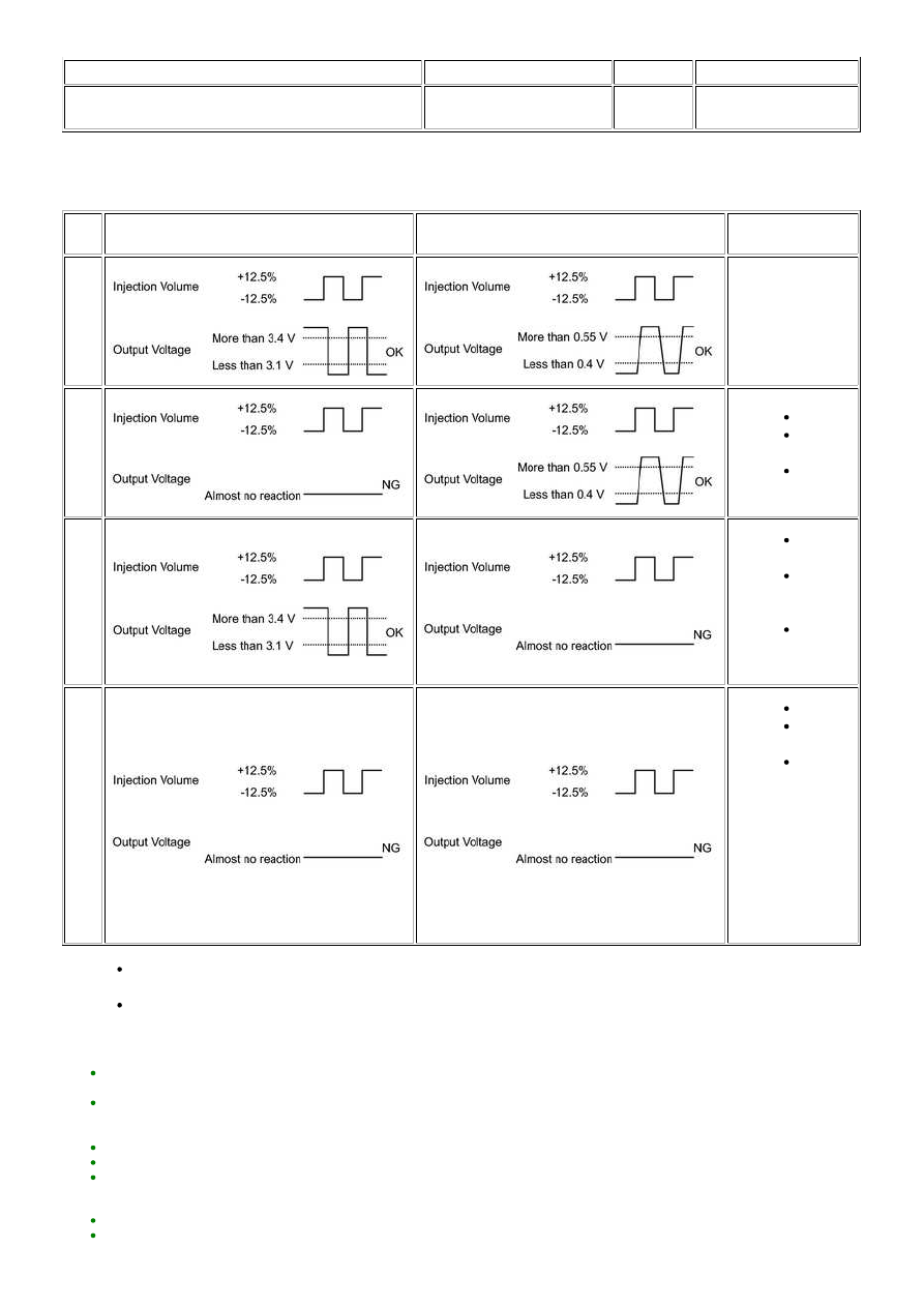
CASE
A/F SENSOR (SENSOR 1) OUTPUT VOLTAGE
HO2 SENSOR (SENSOR 2) OUTPUT VOLTAGE
MAIN SUSPECTED
TROUBLE AREA
1
-
2
A/F sensor
A/F sensor
heater
A/F sensor
circuit
3
HO2
sensor
HO2
sensor
heater
HO2
sensor
circuit
4
Injector
Fuel
pressure
Gas
leakage
from
exhaust
system
(Air-fuel
ratio
extremely
rich or
lean)
Following the Control the Injection Volume for A/F sensor procedure enables technicians to check and graph the voltage
for A/F Sensor / A/F Control System / AFS Voltage B1S1 and O2S B1S2 or AFS Voltage B2S1 and O2S B2S2.
HINT:
If other DTCs relating to different systems that have terminal E2 as the ground terminal are output simultaneously, terminal
E2 may have an open circuit.
Read freeze frame data using the Techstream. Freeze frame data records the engine condition when malfunctions are
detected. When troubleshooting, freeze frame data can help determine if the vehicle was moving or stationary, if the engine
was warmed up or not, if the air-fuel ratio was lean or rich, and other data from the time the malfunction occurred.
If the OX1B wire from the ECM connector is short-circuited to the +B wire, DTC P0136 will be set.
If the OX2B wire from the ECM connector is short-circuited to the +B wire, DTC P0156 will be set.
Bank 1 refers to the bank that includes the No. 1 cylinder*.
*: The No. 1 cylinder is the cylinder which is farthest from the transmission.
Bank 2 refers to the bank that does not include the No. 1 cylinder.
Sensor 1 refers to the sensor closest to the engine assembly.
3UR-FBE ENGINE CONTROL SYSTEM: SFI SYSTEM: P0136-P013...