Toyota Tundra (2015 year). Manual - part 1517


  Index      Toyota     Toyota Tundra (2015 year) - Service and Repair Manual


Search            copyright infringement  


Content   ..  1515  1516  1517  1518   ..


Toyota Tundra (2015 year). Manual - part 1517


4.

READ VALUE USING TECHSTREAM (CHECK FOR SHORT IN WIRE HARNESS)

(a) Disconnect the D7 MAF meter connector.

(b) Connect the Techstream to the DLC3.

(c) Turn the ignition switch to ON.

(d) Turn the Techstream on.

(e) Enter the following menus: Powertrain / Engine and ECT

/ All Data / Intake Air.

(f) Read the value displayed on the Techstream.

Standard value:

-40°C (-40°F)

NG

GO TO STEP 5

OK

REPLACE MASS AIR FLOW METER

5.

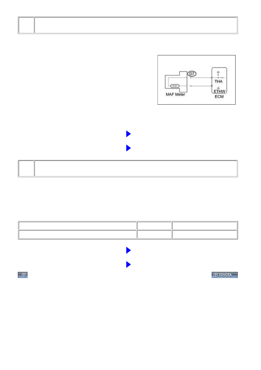
CHECK HARNESS AND CONNECTOR (MASS AIR FLOW METER - ECM)

(a) Disconnect the D7 MAF meter connector.

(b) Disconnect the D74 ECM connector.

(c) Measure the resistance according to the value(s) in the table below.

Standard resistance:

TESTER CONNECTION

CONDITION

SPECIFIED CONDITION

D7-4 (THA) or D74-73 (THA) - Body ground

Always

10 kΩ or higher

NG

REPAIR OR REPLACE HARNESS OR CONNECTOR

OK

REPLACE ECM

3UR-FBE ENGINE CONTROL SYSTEM: SFI SYSTEM: P0112,P0113...

Last Modified: 9-16-2014

6.6 C

Doc ID: RM000000PF50XWX

Model Year: 2015

Model: Tundra

Prod Date Range: [08/2014 -           ]

Title: 3UR-FBE ENGINE CONTROL SYSTEM: SFI SYSTEM: P0115,P0117,P0118; Engine Coolant Temperature

Circuit Malfunction; 2015 MY Tundra [08/2014 -        ]

DTC

P0115

Engine Coolant Temperature Circuit Malfunction

DTC

P0117

Engine Coolant Temperature Circuit Low Input

DTC

P0118

Engine Coolant Temperature Circuit High Input

DESCRIPTION

A thermistor, whose resistance value varies according to the ECT, is built into the Engine Coolant Temperature

(ECT) sensor.

HINT:

When DTC P0115, P0117 or P0118 is set, the ECM enters fail-safe mode. During fail-safe mode, the ECT

is estimated to be 80°C (176°F) by the ECM. Fail-safe mode continues until a pass condition is detected.

DTC

NO.

DTC DETECTION CONDITION

TROUBLE AREA

P0115

Open or short in Engine Coolant Temperature (ECT) sensor

circuit for 0.5 seconds

(1 trip detection logic)

Open or short in ECT

sensor circuit

ECT sensor

ECM

P0117

Short in ECT sensor circuit for 0.5 seconds

(1 trip detection logic)

Short in ECT sensor

ECT sensor

ECM

P0118

Open in ECT sensor circuit for 0.5 seconds

(1 trip detection logic)

Open in ECT sensor circuit

ECT sensor

ECM

HINT:

TEMPERATURE DISPLAYED

MALFUNCTION

-40°C (-40°F)

Open circuit

140°C (284°F) or higher

Short circuit

MONITOR DESCRIPTION

3UR-FBE ENGINE CONTROL SYSTEM: SFI SYSTEM: P0115,P011...

The Engine Coolant Temperature (ECT) sensor is used to monitor the ECT. The ECT sensor has a thermistor

drops. These variations in resistance are reflected in the output voltage from the sensor. The ECM monitors

the sensor voltage and uses this value to calculate the ECT. When the sensor output voltage deviates from the

normal operating range, the ECM interprets this as a fault in the ECT sensor and stores a DTC.

Example:

If the sensor output voltage is more than 4.91 V for 0.5 seconds or more, the ECM determines that there is an

open in the ECT sensor circuit, and stores DTC P0118. Conversely, if the voltage output is less than 0.14 V for

0.5 seconds or more, the ECM determines that there is a short in the sensor circuit, and stores DTC P0117.

If the malfunction is not repaired successfully, a DTC is stored 0.5 seconds after the engine is next started.

MONITOR STRATEGY

Related DTCs

P0115: ECT sensor range check (Fluctuating)

P0117: ECT sensor range check (Low voltage)

P0118: ECT sensor range check (High voltage)

Required Sensors/Components (Main)

ECT sensor

Required Sensors/Components (Related)

-

Duration

0.5 seconds

MIL Operation

Immediate

TYPICAL ENABLING CONDITIONS

Monitor runs whenever following DTCs not stored

None

TYPICAL MALFUNCTION THRESHOLDS

P0115:

ECT sensor voltage

Less than 0.14 V, or more than 4.91 V

P0117:

ECT sensor voltage [ECT]

Less than 0.14 V [More than 135°C (275°F)]

P0118:

ECT sensor voltage [ECT]

More than 4.91 V [Less than -60°C (-76°F)]

COMPONENT OPERATING RANGE

ECT sensor voltage [ECT]

0.14 to 4.91 V [-60 to 135°C (-76 to 275°F)]

CONFIRMATION DRIVING PATTERN

Connect the Techstream to the DLC3.

1. 

3UR-FBE ENGINE CONTROL SYSTEM: SFI SYSTEM: P0115,P011...

Turn the ignition switch to ON and turn the Techstream on.

2. 

Clear DTCs (even if no DTCs are stored, perform the clear DTC operation).

3. 

Turn the ignition switch off and wait for at least 30 seconds.

4. 

Turn the ignition switch to ON and turn the Techstream on.

5. 

Wait 0.5 seconds or more.

6. 

Enter the following menus: Powertrain / Engine and ECT / Trouble Codes.

7. 

Read the pending DTC.

HINT:

If a pending DTC is output, the system is malfunctioning.
If a pending DTC is not output, perform the following procedure.

8. 

Enter the following menus: Powertrain / Engine and ECT / Utility / All Readiness.

9. 

Input the DTC: P0115, P0117 or P0118.

10. 

Check the DTC judgment result.

TESTER

DISPLAY

DESCRIPTION

NORMAL

DTC judgment completed

System normal

ABNORMAL

DTC judgment completed

System abnormal

INCOMPLETE

DTC judgment not completed

Perform driving pattern after confirming DTC enabling conditions

N/A

Unable to perform DTC judgment

11. 

If the test result is INCOMPLETE or N/A and no pending DTC is output, perform a universal trip and

check for permanent DTCs 


.

HINT:

If a permanent DTC is output, the system is malfunctioning.
If no permanent DTC is output, the system is normal.

12. 

WIRING DIAGRAM

3UR-FBE ENGINE CONTROL SYSTEM: SFI SYSTEM: P0115,P011...


Content   ..  1515  1516  1517  1518   ..