Toyota Tundra (2015 year). Manual - part 1515


  Index      Toyota     Toyota Tundra (2015 year) - Service and Repair Manual


Search            copyright infringement  


Content   ..  1513  1514  1515  1516   ..


Toyota Tundra (2015 year). Manual - part 1515


Engine coolant temperature sensor circuit failure (P0115, P0117, P0118)

Not detected

Soak timer circuit failure (P2610)

Not detected

TYPICAL MALFUNCTION THRESHOLDS

After engine stop:

IAT change

Less than 1°C (2°F)

After cold engine start:

IAT change

Less than 1°C (2°F)

CONFIRMATION DRIVING PATTERN

Connect the Techstream to the DLC3.

1. 

Turn the ignition switch to ON and turn the Techstream on.

2. 

Clear DTCs (even if no DTCs are stored, perform the clear DTC operation).

3. 

Turn the ignition switch off and wait for at least 30 seconds.

4. 

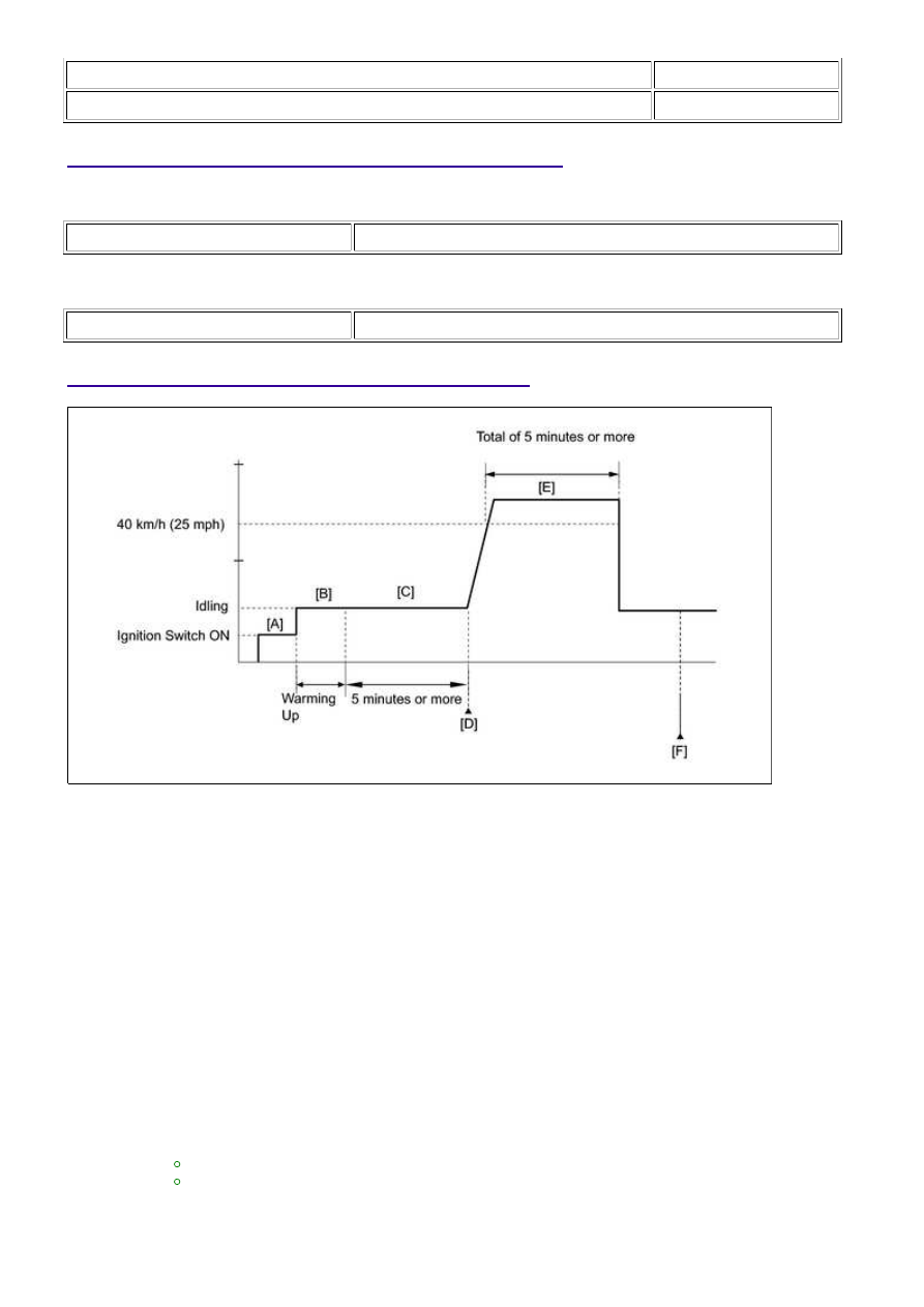
Turn the ignition switch to ON and turn the Techstream on [A].

5. 

Start the engine and warm it up until the engine coolant temperature reaches 75°C (167°F) or

higher [B].

6. 

Idle the engine for 5 minutes or more [C].

HINT:

During steps [A] through [C], if the change in the intake air temperature is below 1°C

(1.8°F), the intake air temperature sensor (MAF meter) is malfunctioning. It is not necessary
to continue this procedure.

7. 

Enter the following menus: Powertrain / Engine and ECT / Trouble Codes [D].

8. 

Read the pending DTC.

HINT:

If a pending DTC is output, the system is malfunctioning.
If a pending DTC is not output, perform the following procedure.

9. 

Enter the following menus: Powertrain / Engine and ECT / Utility / All Readiness.

10. 

Input the DTC: P0111.

11. 

3UR-FBE ENGINE CONTROL SYSTEM: SFI SYSTEM: P0111; Intak...

Check the DTC judgment result.

TESTER

DISPLAY

DESCRIPTION

NORMAL

DTC judgment completed

System normal

ABNORMAL

DTC judgment completed

System abnormal

INCOMPLETE

DTC judgment not completed

Perform driving pattern after confirming DTC enabling conditions

N/A

Unable to perform DTC judgment

CAUTION:

When performing the confirmation driving pattern, obey all speed limits and traffic laws.

HINT:

If the judgment result shows ABNORMAL, the system has a malfunction.
If the judgment result shows INCOMPLETE or N/A, perform steps [E] through [F].

12. 

Check the DTC judgment result again [F].

HINT:

If the judgment result shows INCOMPLETE or N/A, perform steps [E] through [F] again.

14. 

If no pending DTC is output, perform a universal trip and check for permanent DTCs 


.

HINT:

If a permanent DTC is output, the system is malfunctioning.
If no permanent DTC is output, the system is normal.

15. 

WIRING DIAGRAM

Refer to DTC P0112 


.

INSPECTION PROCEDURE

HINT:

Read freeze frame data using the Techstream. Freeze frame data record the engine condition when

malfunctions are detected. When troubleshooting, freeze frame data can help determine if the vehicle
was moving or stationary, if the engine was warmed up or not, if the air-fuel ratio was lean or rich, and
other data, from the time the malfunction occurred.

PROCEDURE

1.

CHECK ANY OTHER DTCS OUTPUT (IN ADDITION TO DTC P0111)

(a) Connect the Techstream to the DLC3.

(b) Turn the ignition switch to ON.

3UR-FBE ENGINE CONTROL SYSTEM: SFI SYSTEM: P0111; Intak...

(c) Turn the Techstream on.

(d) Enter the following menus: Powertrain / Engine and ECT / Trouble Codes.

(e) Read DTCs.

Result

DISPLAY (DTC OUTPUT)

PROCEED TO

P0111 and other DTCs are output

A

P0111 is output

B

HINT:

If any DTCs other than P0111 are output, troubleshoot those DTCs first.

B

REPLACE MASS AIR FLOW METER

A

GO TO DTC CHART

3UR-FBE ENGINE CONTROL SYSTEM: SFI SYSTEM: P0111; Intak...

Last Modified: 9-16-2014

6.6 C

Doc ID: RM000000PF30VFX

Model Year: 2015

Model: Tundra

Prod Date Range: [08/2014 -           ]

Title: 3UR-FBE ENGINE CONTROL SYSTEM: SFI SYSTEM: P0112,P0113; Intake Air Temperature Circuit Low

Input; 2015 MY Tundra [08/2014 -        ]

DTC

P0112

Intake Air Temperature Circuit Low Input

DTC

P0113

Intake Air Temperature Circuit High Input

DESCRIPTION

The Intake Air Temperature (IAT) sensor, mounted on the Mass Air Flow (MAF) meter, monitors the

IAT. The IAT sensor has a built-in thermistor with a resistance that varies according to the temperature

voltage changes (See Fig. 1).

changes, according to changes in the IAT, the voltage at terminal THA also varies. Based on this signal,

the ECM increases the fuel injection volume when the engine is cold to improve driveability.

HINT:

When DTC P0112 or P0113 is set, the ECM enters fail-safe mode. During fail-safe mode, the IAT

is estimated to be 20°C (68°F) by the ECM. Fail-safe mode continues until a pass condition is
detected.

DTC

NO.

DTC DETECTION CONDITION

TROUBLE AREA

P0112

Short in Intake Air Temperature (IAT) sensor circuit for

0.5 seconds

(1 trip detection logic)

Short in IAT sensor circuit

IAT sensor (built into MAF

meter)

ECM

3UR-FBE ENGINE CONTROL SYSTEM: SFI SYSTEM: P0112,P0113...


Content   ..  1513  1514  1515  1516   ..