Toyota Tundra (2015 year). Manual - part 140
Last Modified: 9-16-2014
6.6 C
Doc ID: RM000004UD300WX
Model Year: 2015
Model: Tundra
Prod Date Range: [08/2014 - ]
Title: PARK ASSIST / MONITORING: BLIND SPOT MONITOR SYSTEM: C1AB2; Short to GND in Outer Mirror
Indicator(Master); 2015 MY Tundra [08/2014 - ]
DTC
C1AB2
Short to GND in Outer Mirror Indicator(Master)
DESCRIPTION
This DTC is stored when the blind spot monitor sensor RH detects a ground short in the blind spot monitor
indicator RH.
DTC
CODE
DTC DETECTION CONDITION
TROUBLE AREA
C1AB2
With the blind spot monitor main switch assembly (warning
canceling switch assembly) on, the voltage output from the blind
spot monitor sensor to the indicator is low for a certain amount of
time.
Harness or connector
Outer rear view
mirror assembly RH
Outer rear view
mirror sub-assembly
RH
Blind spot monitor
sensor RH
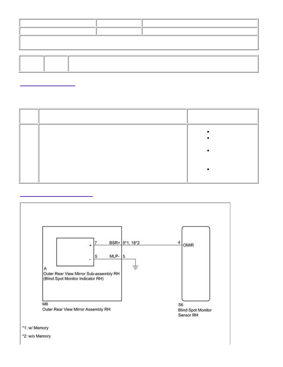
WIRING DIAGRAM
PARK ASSIST / MONITORING: BLIND SPOT MONITOR SYSTEM:...