Content .. 1365 1366 1367 1368 ..
Toyota Tundra (2015 year). Manual - part 1367
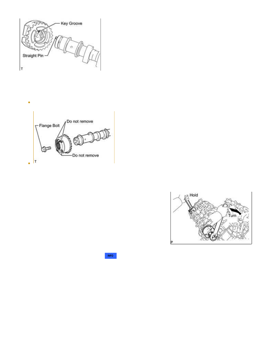
NOTICE:
Torque:
100 N·m {1020 kgf·cm, 74ft·lbf}
(g) Remove the camshaft bearing cap
.
(h) Check the camshaft timing exhaust gear lock.
(1) Make sure that the camshaft timing exhaust gear is locked.
1UR-FE ENGINE MECHANICAL: ENGINE UNIT: INSPECTION; 20...