Toyota Tundra (2015 year). Manual - part 1365


  Index      Toyota     Toyota Tundra (2015 year) - Service and Repair Manual


Search            copyright infringement  


Content   ..  1363  1364  1365  1366   ..


Toyota Tundra (2015 year). Manual - part 1365


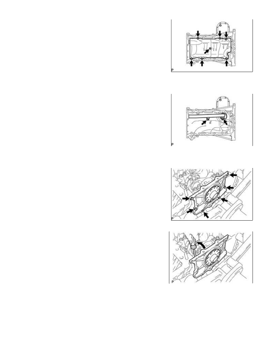
(a) Remove the 7 bolts and baffle plate.

50. REMOVE OIL STRAINER SUB-ASSEMBLY

(a) Remove the 2 bolts, oil strainer and O-ring.

51. REMOVE ENGINE REAR OIL SEAL RETAINER

(a) Remove the 6 bolts and oil seal retainer.

(b) Using a screwdriver, pry out the oil seal retainer.

HINT:

Tape the screwdriver tip before use.

52. REMOVE OIL DRAIN PIPE SUB-ASSEMBLY

1UR-FE ENGINE MECHANICAL: ENGINE UNIT: DISASSEMBLY; ...

(a) Remove the bolt and oil drain pipe.

(b) Remove the O-ring.

53. REMOVE REAR CRANKSHAFT OIL SEAL

(a) Place the oil seal retainer on wooden blocks.

(b) Using a screwdriver and hammer, tap out the oil seal.

54. REMOVE RING PIN

NOTICE:

It is not necessary to remove the ring pin unless it is being replaced.

55. REMOVE STUD BOLT

NOTICE:

If the stud bolt is deformed or its threads are damaged, replace it.

1UR-FE ENGINE MECHANICAL: ENGINE UNIT: DISASSEMBLY; ...

Last Modified: 9-16-2014

6.6 G

Doc ID: RM0000030XL04NX

Model Year: 2015

Model: Tundra

Prod Date Range: [08/2014 -           ]

Title: 1UR-FE ENGINE MECHANICAL: ENGINE UNIT: INSPECTION; 2015 MY Tundra [08/2014 -        ]

INSPECTION

1. INSPECT CYLINDER HEAD SET BOLT

Standard length:

141.3 to 142.7 mm (5.56 to 5.62 in.)

Maximum length:

143.7 mm (5.66 in.)

If the length is more than the maximum, replace the cylinder

head bolt.

103 mm (4.06 in.) for intake side bolt.

108 mm (4.25 in.) for exhaust side bolt.

Standard diameter:

10.85 to 11.00 mm (0.427 to 0.433 in.)

Minimum diameter:

10.60 mm (0.417 in.)

If the diameter is less than the minimum, replace the cylinder head bolt.

HINT:

2. INSPECT NO. 1 VALVE ROCKER ARM SUB-ASSEMBLY

(a) Turn the roller by hand to check that it turns smoothly.

If the roller does not turn smoothly, replace the valve rocker

arm.

1UR-FE ENGINE MECHANICAL: ENGINE UNIT: INSPECTION; 20...

3. INSPECT VALVE LASH ADJUSTER ASSEMBLY

NOTICE:

Keep the adjuster free from dirt and foreign objects.
Use only clean engine oil.

to press down on the check ball inside the plunger.

SST: 09276-75010

(c) Squeeze SST and the lash adjuster together to move the

plunger up and down 5 to 6 times.

Plunger moves up and down.

NOTICE:

When bleeding high-pressure air from the compression chamber,

firmly press the plunger with your fingers.

OK:

Plunger can be pressed 3 times.

If the plunger can still be compressed after pressing it 3 times,

replace the lash adjuster with a new one.

4. INSPECT CAMSHAFT SUB-ASSEMBLY

(a) Inspect the camshaft for runout.

(1) Place the camshaft on V-blocks.

(2) Using a dial indicator, measure the circle runout at the center journal.

Maximum circle runout:

0.04 mm (0.00157 in.)

If the circle runout is more than the maximum, replace the camshaft.

HINT:

Check the oil clearance after replacing the camshaft.

1UR-FE ENGINE MECHANICAL: ENGINE UNIT: INSPECTION; 20...


Content   ..  1363  1364  1365  1366   ..