Toyota Tundra (2015 year). Manual - part 1345


  Index      Toyota     Toyota Tundra (2015 year) - Service and Repair Manual


Search            copyright infringement  


Content   ..  1343  1344  1345  1346   ..


Toyota Tundra (2015 year). Manual - part 1345


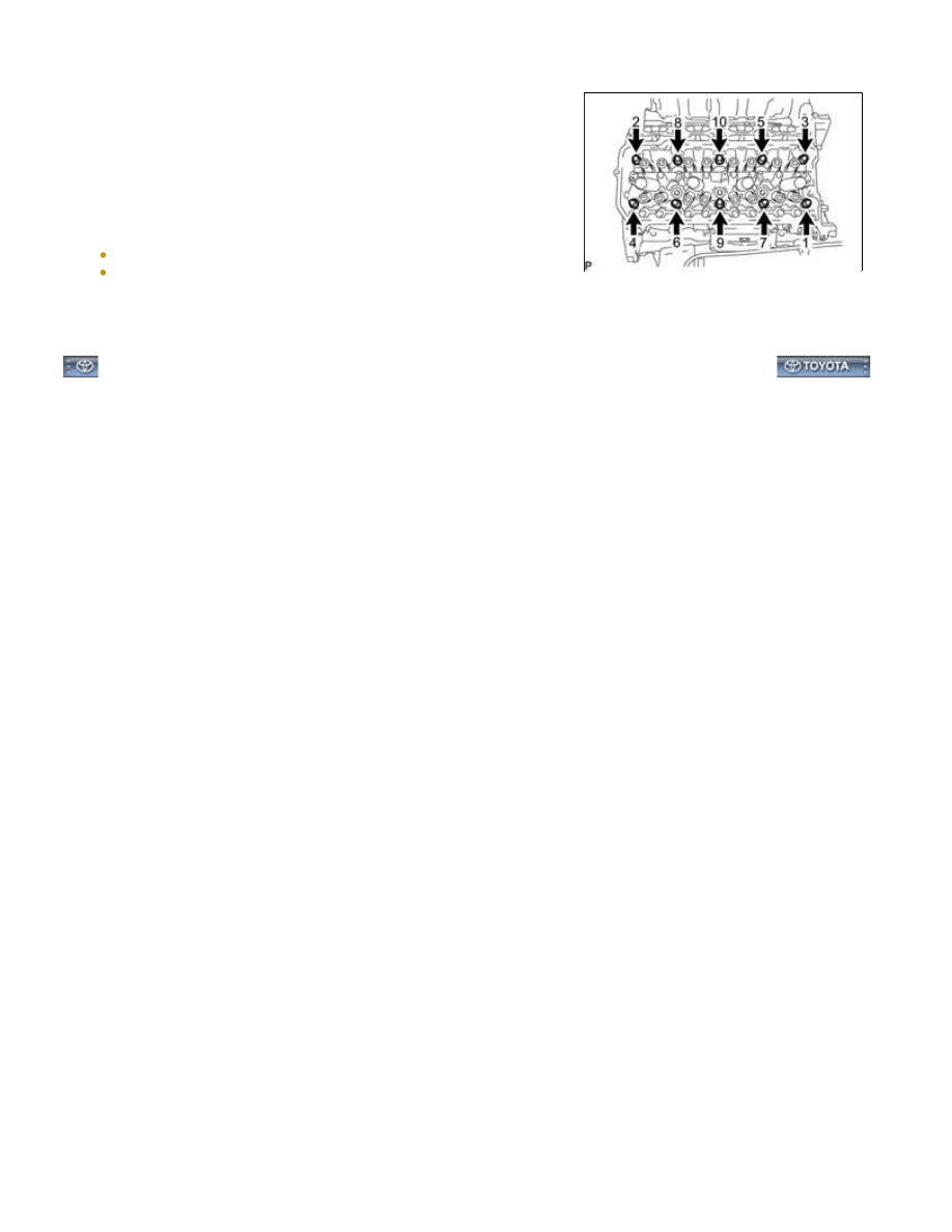
(b) Using a 10 mm bi-hexagon wrench, uniformly loosen the 10

cylinder head bolts in the sequence shown in the illustration.

Remove the 10 cylinder head bolts and plate washers.

HINT:

Be sure to arrange the removed parts for each installation

position separately.

NOTICE:

Be careful not to drop washers into the cylinder head.
Head warpage or cracking could result from removing bolts in an
incorrect order.

7. REMOVE CYLINDER HEAD GASKET RH

1UR-FE ENGINE MECHANICAL: CYLINDER HEAD GASKET (for...

Last Modified: 9-16-2014

6.6 A

Doc ID: RM000002S5304IX

Model Year: 2015

Model: Tundra

Prod Date Range: [08/2014 -           ]

Title: 1UR-FE ENGINE MECHANICAL: CYLINDER HEAD GASKET (for Bank 2): INSTALLATION; 2015 MY Tundra

[08/2014 -        ]

INSTALLATION

HINT:

Perform "Inspection After Repairs" after replacing the cylinder head sub-assembly RH 


.

1. INSPECT CYLINDER HEAD SET BOLT 

2. INSPECT CYLINDER HEAD SUB-ASSEMBLY RH 

3. INSTALL CYLINDER HEAD GASKET RH

(a) Check the piston protrusions for each cylinder.

(1) Clean the cylinder block with solvent.

HINT:

Perform "Inspection After Repairs" after replacing the cylinder head sub-assembly RH 


.

(a) Place the cylinder head on the cylinder block.

NOTICE:

The cylinder head bolts are tightened in 3 progressive steps.

(c) Step 1:

(1) Using a 10 mm bi-hexagon wrench, install and uniformly

tighten the 10 cylinder head bolts with the plate washers in

several steps, in the sequence shown in the illustration.

Torque:

36 N·m {367 kgf·cm, 27ft·lbf}

(d) Step 2:

(1) Mark each cylinder head bolt head with paint as shown in the

illustration.

(2) Tighten the cylinder head bolts another 90° in the sequence

shown in step 1.

(e) Step 3:

(1) Tighten the cylinder head bolts an additional 90° in the sequence shown in step 1.

(2) Check that the painting marks are now facing rearward.

(f) Install and uniformly tighten the 2 bolts in the sequence shown

in the illustration.

Torque:

21 N·m {214 kgf·cm, 15ft·lbf}

5. INSTALL VALVE STEM CAP

6. INSTALL VALVE LASH ADJUSTER ASSEMBLY

(a) Inspect the valve lash adjuster 


.

(b) Install the 16 valve lash adjusters to the cylinder head.

NOTICE:

Install the lash adjuster at the same place it was removed from.

7. INSTALL NO. 1 VALVE ROCKER ARM SUB-ASSEMBLY

(a) Apply engine oil to the lash adjuster tips and valve stem cap ends.

1UR-FE ENGINE MECHANICAL: CYLINDER HEAD GASKET (for...

(b) Install the valve rocker arms as shown in the illustration.

8. INSTALL CAMSHAFTS (for Bank 2)

(a) Install the camshafts 


.

9. INSTALL EXHAUST MANIFOLD SUB-ASSEMBLY RH

(a) Install the exhaust manifold RH 


.

1UR-FE ENGINE MECHANICAL: CYLINDER HEAD GASKET (for...


Content   ..  1343  1344  1345  1346   ..