Content .. 1342 1343 1344 1345 ..
Toyota Tundra (2015 year). Manual - part 1344
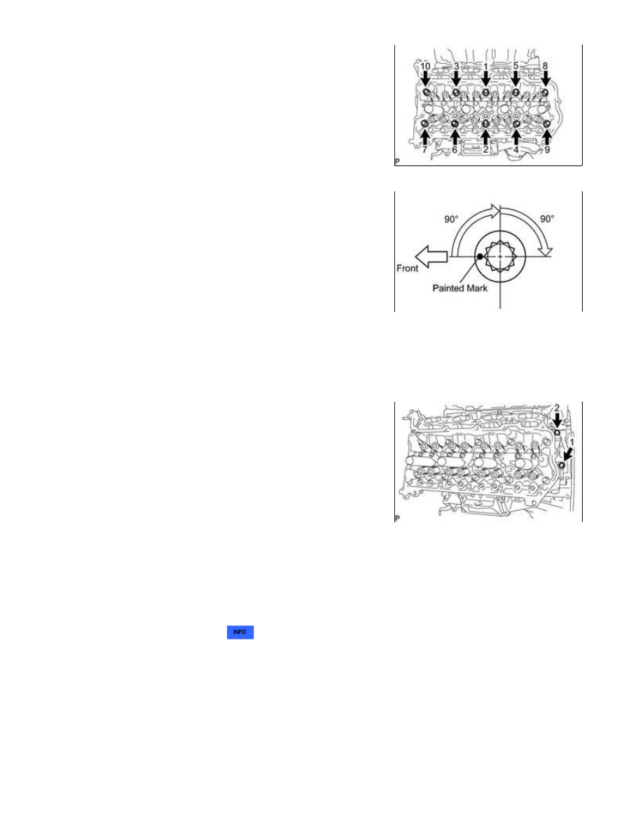
(c) Step 1:
(1) Using a 10 mm bi-hexagon wrench, install and uniformly
tighten the 10 cylinder head bolts with the plate washers in
several steps, in the sequence shown in the illustration.
Torque:
36 N·m {367 kgf·cm, 27ft·lbf}
(d) Step 2:
(1) Mark each cylinder head bolt head with paint as shown in the
illustration.
(2) Tighten the cylinder head bolts another 90° in the sequence
shown in step 1.
(e) Step 3:
(1) Tighten the cylinder head bolts an additional 90° in the sequence shown in step 1.
(2) Check that the painted marks are now facing rearward.
(f) Install and uniformly tighten the 2 bolts in the sequence shown
in the illustration.
Torque:
21 N·m {214 kgf·cm, 15ft·lbf}
5. INSTALL VALVE STEM CAP
6. INSTALL VALVE LASH ADJUSTER ASSEMBLY
(a) Inspect the valve lash adjuster
.
(b) Install the 16 lash adjusters to the cylinder head.
NOTICE:
Install the lash adjuster at the same place it was removed from.
7. INSTALL NO. 1 VALVE ROCKER ARM SUB-ASSEMBLY
(a) Apply engine oil to the lash adjuster tips and valve stem cap ends.
1UR-FE ENGINE MECHANICAL: CYLINDER HEAD GASKET (for...