Toyota Tundra (2015 year). Manual - part 1329


  Index      Toyota     Toyota Tundra (2015 year) - Service and Repair Manual


Search            copyright infringement  


Content   ..  1327  1328  1329  1330   ..


Toyota Tundra (2015 year). Manual - part 1329


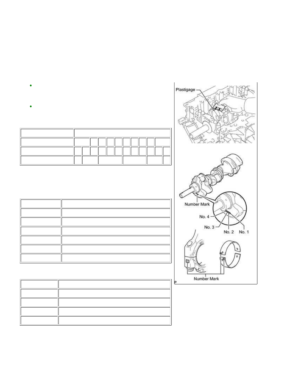
(n) Measure the Plastigage at its widest point.

Standard oil clearance:

0.025 to 0.050 mm (0.000984 to 0.00197 in.)

Maximum oil clearance:

0.070 mm (0.00276 in.)

If the oil clearance is more than the maximum, replace the

bearings. If necessary, replace the crankshaft.

HINT:

If replacing a bearing, replace it with one that has the same
number as its respective connecting rod cap. Each bearing's
standard thickness is indicated by a 1, 2, 3 or 4 mark on its
surface.
Select the correct bearing by adding together the number marks
imprinted on the connecting rod big end and crankshaft.

Standard Bearing Chart:

ITEM

NUMBER MARK

Connecting rod

1

2

1

2

3

2

3

4

3

4

Crankshaft

1

2

1

3

2

1

3

2

1

3

2

3

Use bearing

2

3

4

5

6

7

EXAMPLE:

Connecting rod "1" + Crankshaft "2" = 3 (Use bearing "3")

Standard Sized Bearing Center Wall Thickness:

NUMBER MARK

SPECIFIED CONDITION

2

1.489 to 1.492 mm (0.0586 to 0.0587 in.)

3

1.492 to 1.495 mm (0.0587 to 0.0589 in.)

4

1.495 to 1.498 mm (0.0589 to 0.0590 in.)

5

1.498 to 1.501 mm (0.0590 to 0.0591 in.)

6

1.501 to 1.504 mm (0.0591 to 0.0592 in.)

7

1.504 to 1.507 mm (0.0592 to 0.0593 in.)

Connecting Rod Big End Inside Diameter:

NUMBER MARK

SPECIFIED CONDITION

1

56.000 to 56.006 mm (2.20472 to 2.20496 in.)

2

56.006 to 56.012 mm (2.20496 to 2.20519 in.)

3

56.012 to 56.018 mm (2.20519 to 2.20543 in.)

4

56.018 to 56.024 mm (2.20543 to 2.20566 in.)

Crankshaft Pin Diameter:

1UR-FE ENGINE MECHANICAL: CYLINDER BLOCK: DISASSE...

NUMBER MARK

SPECIFIED CONDITION

1

52.994 to 53.000 mm (2.08637 to 2.08661 in.)

2

52.988 to 52.994 mm (2.08614 to 2.08637 in.)

3

52.982 to 52.988 mm (2.08590 to 2.08614 in.)

(o) Completely remove the Plastigage.

(p) Perform the inspection above for each cylinder.

3. REMOVE PISTON AND CONNECTING ROD

(b) Remove the 16 cap bolts, 8 connecting rod caps and 8 lower bearings.

Arrange the piston and connecting rod in the correct order.

4. REMOVE CONNECTING ROD BEARING

(a) Remove the connecting rod bearings from the connecting rods and connecting rod caps.

HINT:

Arrange the removed parts in the correct order.

5. REMOVE PISTON RING SET

HINT:

Arrange the piston rings in the correct order.

(a) Using a piston ring expander, remove the 2 compression rings.

(b) Remove the 2 side rails and oil ring expander by hand.

6. REMOVE PISTON WITH PIN SUB-ASSEMBLY

1UR-FE ENGINE MECHANICAL: CYLINDER BLOCK: DISASSE...

(a) Disconnect the connecting rod from the piston.

(1) Using a small screwdriver, pry off the 2 snap rings from the

piston.

(2) Gradually heat the piston to approximately 80°C (176°F).

(3) Using a brass bar and plastic-faced hammer, lightly tap out

the piston pin. Then remove the connecting rod.

HINT:

The piston and pin are a matched set.
Arrange the pistons, pins, rings, connecting rods and bearings in
the correct order.

(b) Clean the piston.

(1) Using a gasket scraper, remove the carbon from the piston

top.

1UR-FE ENGINE MECHANICAL: CYLINDER BLOCK: DISASSE...

(2) Using a groove cleaning tool or broken ring, clean the piston

ring grooves.

(3) Using solvent and a brush, thoroughly clean the piston.

NOTICE:

Do not use a wire brush.

7. INSPECT CRANKSHAFT THRUST CLEARANCE

(a) Using a dial indicator, measure the thrust clearance while prying

the crankshaft back and forth with a screwdriver.

Standard thrust clearance:

0.020 to 0.220 mm (0.000787 to 0.00866 in.)

Maximum thrust clearance:

0.30 mm (0.0118 in.)

If the thrust clearance is more than the maximum, replace the

thrust washers as a set.

Standard thrust washer thickness:

2.44 to 2.49 mm (0.0961 to 0.0980 in.)

If necessary, replace the crankshaft.

8. REMOVE CRANKSHAFT

(a) Uniformly loosen and remove the 10 bearing cap bolts and 10

seal washers in several steps, in the sequence shown in the

illustration.

1UR-FE ENGINE MECHANICAL: CYLINDER BLOCK: DISASSE...


Content   ..  1327  1328  1329  1330   ..