Toyota Tundra (2015 year). Manual - part 1313


  Index      Toyota     Toyota Tundra (2015 year) - Service and Repair Manual


Search            copyright infringement  


Content   ..  1311  1312  1313  1314   ..


Toyota Tundra (2015 year). Manual - part 1313


OK

NG

REPAIR OR REPLACE HARNESS OR CONNECTOR

OK

REPLACE ECM

4.

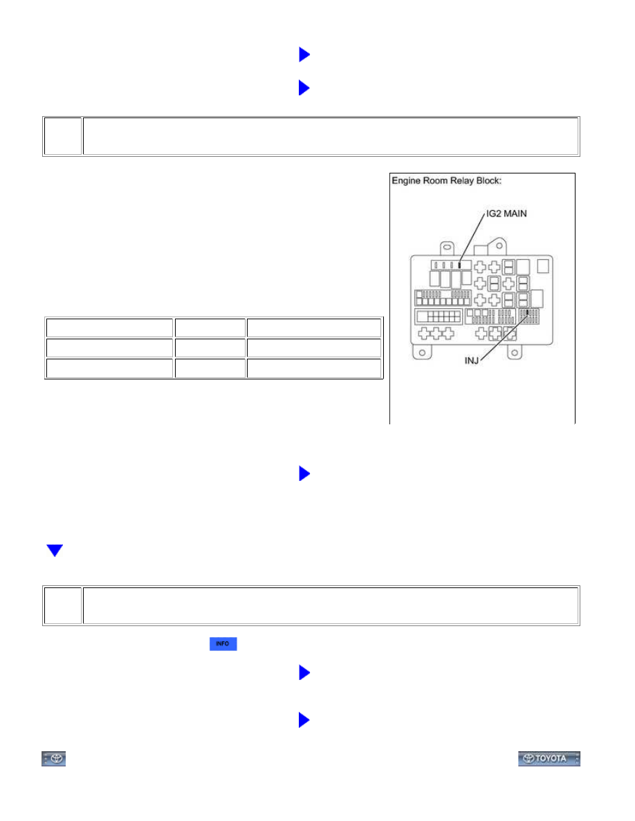
INSPECT FUSES (INJ, IG2 MAIN)

(a) Remove the INJ fuse and IG2 MAIN fuse from the engine

room relay block.

(b) Measure the resistance according to the value(s) in the table

below.

Standard Resistance:

TESTER CONNECTION

CONDITION

SPECIFIED CONDITION

INJ fuse

Always

Below 1 Ω

IG2 MAIN fuse

Always

Below 1 Ω

NG

CHECK FOR SHORT IN ALL HARNESSES AND

CONNECTORS CONNECTED TO FUSE AND REPLACE

FUSE

5.

INSPECT INTEGRATION RELAY (IG2)

(a) Inspect the integration relay 


.

NG

REPLACE INTEGRATION RELAY

OK

REPAIR OR REPLACE HARNESS OR CONNECTOR

(INTEGRATION RELAY - FUEL INJECTOR

ASSEMBLY)

1UR-FE ENGINE CONTROL SYSTEM: SFI SYSTEM: Fuel Injector C...

Last Modified: 9-16-2014

6.6 J

Doc ID: RM000001FLC08TX

Model Year: 2015

Model: Tundra

Prod Date Range: [08/2014 -           ]

Title: 1UR-FE ENGINE CONTROL SYSTEM: SFI SYSTEM: Cranking Holding Function Circuit; 2015 MY Tundra

[08/2014 -        ]

Cranking Holding Function Circuit

DESCRIPTION

The cranking holding control system keeps energizing the starter relay from when the ECM detects the starter

starter relay through the park/neutral position switch, and then, the engine is cranked. When the ECM receives a

stable engine speed signal (NE signal), more specifically, when the NE signal reaches a predetermined value, the

ECM stops outputting the STAR signal.

Also, the ECM monitors the starter relay operating conditions based on the STA terminal voltage status.

WIRING DIAGRAM

1UR-FE ENGINE CONTROL SYSTEM: SFI SYSTEM: Cranking Hold...

INSPECTION PROCEDURE

PROCEDURE

1.

READ VALUE USING TECHSTREAM (STARTER SIGNAL)

(a) Connect the Techstream to the DLC3.

(b) Turn the ignition switch to ON.

(c) Turn the Techstream on.

(d) Enter the following menus: Powertrain / Engine and ECT / Data List / Starter Signal.

(e) Check the result when the ignition switch is turned to the ON and START positions.

OK:

1UR-FE ENGINE CONTROL SYSTEM: SFI SYSTEM: Cranking Hold...

OK

IGNITION SWITCH CONDITION

STARTER SIGNAL

ON

OFF

START

ON

NG

GO TO STEP 2

OK

PROCEED TO NEXT CIRCUIT INSPECTION SHOWN

IN PROBLEM SYMPTOMS TABLE

2.

INSPECT ECM (STSW TERMINAL VOLTAGE)

(a) Disconnect the ECM connector.

(b) Perform the cranking operation.

(c) Measure the voltage according to the value(s) in the table

below.

Standard Voltage:

TESTER CONNECTION

IGNITION SWITCH

CONDITION

SPECIFIED

CONDITION

A24-14 (STSW) - Body

ground

ON

Below 1 V

START

9 to 13 V

HINT:

DTCs related to the communication with other computers may be

set due to this inspection. Clear those DTCs after the inspection.

NG

GO TO STEP 7

3.

INSPECT ECM (STAR TERMINAL OUTPUT VOLTAGE)

1UR-FE ENGINE CONTROL SYSTEM: SFI SYSTEM: Cranking Hold...


Content   ..  1311  1312  1313  1314   ..