Content .. 1312 1313 1314 1315 ..
Toyota Tundra (2015 year). Manual - part 1314
OK
OK
(a) Connect the Techstream to the DLC3.
(b) Turn the ignition switch to ON.
(c) Turn the Techstream on.
(d) Enter the following menus: Powertrain / Engine and ECT /
Active Test / Control the All Cylinders Fuel Cut.
(e) Measure the voltage according to the value(s) in the table
below.
Standard Voltage:
TESTER CONNECTION
SWITCH CONDITION
SPECIFIED
CONDITION
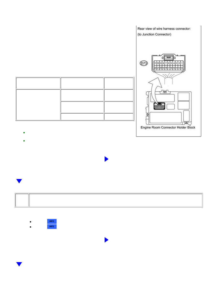
D73-6 (Junction
Connector) - Body
ground
Ignition switch ON (shift
lever in P or N)
Below 1 V
Ignition switch ON (shift
lever not in P or N)
9 to 13 V
Cranking operation
9 to 13 V
HINT:
The junction connector is in the engine room connector holder
block as shown in the illustration.
During this inspection, all connectors and relays should be
connected.
NG
GO TO STEP 8
4.
INSPECT PARK/NEUTRAL POSITION SWITCH ASSEMBLY
(a) Inspect Park/Neutral Position (PNP) switch assembly.
for 2WD
for 4WD
NG
REPLACE PARK/NEUTRAL POSITION SWITCH
ASSEMBLY
1UR-FE ENGINE CONTROL SYSTEM: SFI SYSTEM: Cranking Hold...